Facebook
 Google
 GitHub
 Linkedin
I'm currently doing a project where I need to check the battery protection circuit of a LiPo .
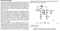
My current setup is a 12v supply from which by making use of LM317,Arduino(i vary the Vadj) to get a voltage range of 2V ~ 5V output.
when i connect the charger it would produce 4.2V at the 3.7V (output of the LM317).
I'm not clear as to how LM317 handles reverse current and how much it can handle ?
My aim is to check the outputs Discharging,Charging over the different voltage range ( 2V ~ 5V).
How do i protect my test setup so that varying the bat_voltage(LM317 outputs) does not affect/burn the setup when i connect the charger.
Thanks