LM311 Not working as expected

Thread Starter

SamR

Joined Mar 19, 2019
5,042
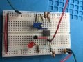
New to comparators and breadboarded this to play with. Voltage divider to provide 2.5V reference voltage on inverting input, potentiometer to vary noninverting input 0-5V, 2N2222 on output to drive LED for output visual confirmation. It works, but turns on at 0.11V??? What is going on here that I am missing? The LM311 is rated to sink 50mA so the 2N2222 shouldn't be needed.lm311-comparator.png
 

Thread Starter

SamR

Joined Mar 19, 2019
5,042
Have you measured 2.5 Volts at Pin #3 of the LM311 ?
Yes which is why I am confused. I also replaced the chip and swapped pin 2&3 inputs. Let me rebreadboard it try again. Will post results in a bit.
 

bertus

Joined Apr 5, 2008
22,277
Hello,

What happens when you disconnect the pins 5 and 6?
This is what can be done with the pins 5 and 6:

LM311_what_to_do_with_pins_5_and_6.png

Bertus
 

mvas

Joined Jun 19, 2017
539
If offset balancing is not used, the BALANCE and BAL/STRB pins must be unconnected.
It is also acceptable to short pins together.
 

mvas

Joined Jun 19, 2017
539
Disconnect R4, Q1 and LED.
See if the Voltage changes at Pin #7 with just R5 connected.

What does "... 5V (TO +/-15V) ..." mean in your schematic?
 

Thread Starter

SamR

Joined Mar 19, 2019
5,042
OK I breadboarded it again. First I found that my bench power supply was clamped @ 20mA max so I upped it to 50mA. Shorting unused strobe pins 5&6 or not makes no difference. Pin 7 measures 0.75V OFF and when input reaches 2.48V rising the comparator turns ON and pin 7 reads 0.67V. With the PS clamped @ 20mA the LED will blip on and off at the transition, but not when I upped the clamp to 50mA. Idling the PS current is 0.000A, after the transition it is 0.042A and the LED does not light at all. The resistor on pin 7 seems to be incorrectly sized and I cannot get the LED to light even by eliminating the xstor and tying the LED directly to pin7 with the pull up 560 ohm resistor used instead of the 10K.
 

Attachments

Thread Starter

SamR

Joined Mar 19, 2019
5,042
Fixed it by dropping the pull up resistor to 1K, but now the LED comes on and then after a few seconds starts to dim to out. Replaced the LED and got the same result. Is something getting overloaded in the LM386? or the xstor? I can drop the input voltage sinking the pull up to gnd and wait a bit and get the same result. So it has to be leakage in the comparator or the xstor?
 

Thread Starter

SamR

Joined Mar 19, 2019
5,042
I am so close to getting it right, or I think I am... Replaced the R5 pullup resistor with a 1k pot and the circuit seemed to work fine at about 470 ohms on the R5 pot so I started substituting fixed resistors for the R5. Just when I thought I had it the LED would dim again after it's initial bright start. Changed the LED current limiting resistor value with no real success. Something is leaking and I think it's the comparator. The circuit is using ~52mA when the comparator is ON and 11mA when it's OFF. So the LED and xstor are pulling ~40mA which seems a lot for switching a 2N2222 w/ externally powered LED. Oh well... Long day and getting late so time to pull the plug for tonight. More fun tomorrow. Hmmm... maybe a low current LED...
 

sghioto

Joined Dec 31, 2017
5,390
You are correct you don't need the transistor. The output of the LM311 is an open collector transistor.
SG
EEE Lm311.PNG
EEE Lm311.PNG
Or if using the transistor as an emitter follower
EEE Lm311.PNG
 
Last edited:

mvas

Joined Jun 19, 2017
539
When LED is ON ...

0.25 ma = R2 + R3
0.50 ma = R4
5.00 ma = LM 311
3.00 ma = R5 ( was 10k, now 1k? )
7.00 ma = LED + R4
=============
15.75 ma = Total (approx)

How is the circuit in Message #1 drawing 42 ma ? ( per reply #7 )
 
Last edited:

MrChips

Joined Oct 2, 2009
30,810
My breadboard power supply is fixed at 5V and can deliver 1A. I never have to worry about it when prototyping circuits.
 

sghioto

Joined Dec 31, 2017
5,390
My breadboard power supply is fixed at 5V and can deliver 1A.
Yeah but what happens if you accidentally plug a chip or something polarity sensitive in backwards? That's why you have supplies with current limits. I normally set mine at 100ma with low voltage circuits.
SG
 

BobaMosfet

Joined Jul 1, 2009
2,113
@SamR
There are too many things wrong in your original circuit which is what is confusing you. First, R5 should be eliminated. You should have a current limiting resistor on the base on the 2N2222 to prevent the OpAmp from overdriving it. In order to size that properly you need to understand how to calculate it based on the maximum current output your LED (or Ice) should be allowed to carry (taking into account the voltage drop for Ve and the 'load' LED). R4 should be eliminated, and the LED should be connected in series on the collector side. It is the combination of the OpAmp, base-resistor, and 2N2222 that controls the current level through the LED. Placing the LED on the emitter side of the 2N2222, in this case, creates a ground-loop to the inverting input, so it is best to put it on the collector side.
 

Thread Starter

SamR

Joined Mar 19, 2019
5,042
I keep the PS amps clamped low because I'm usually working with logic circuits and don't want to cook them if I miss wire something. Yes the mA drain is puzzling me as it is more than double what I expected. There is somethin unexpected going on here (which is why I posted this). I knew the output 2N2222 should not have been needed, but added it due to the large mA being sank and thought it may have been due to the LED (it isn't). Placing the LED emitter following didn't work, but led me down a new path with surprising results. I eliminated the xstor, used a pot for the R5 pullup and still had the same bright light at first and dimming quickly results. So I started thinking outside the box and played some what ifs with the circuit and found this. I eliminated R5 pullup and tied the LED directly to the 311 Pin7 output. I moved the pullup pot to between Pin1 and Gnd. It works, but now pull 61mA when off and lighting the LED. I hooked up my scope to Pin7 and watched the output voltage. It starts to rise when Pin2 reaches 2.48V. Pin7 slowly increases as voltage to Pin7 drops? There is no sharp "digital" output , it ramps up "analog". Even stranger is that as I decrease the voltage to Pin2 the circuit current rises from 0 to61mA at 2.48V and at 1.48V it drops off sharply to 40mA, then at 1.38V it goes back up again. Something is going on here that I don't understand. There is NO pullup resistor and the Pin7 output is powered? It is listed as being FL (floating voltage) output instead of open collector which I don't really understand what FL is. This seems to be the crux of my problem. I already tried the LM741 and LM339 and they worked perfectly and are OC (the 741 is actually an Op-Amp used as a comparator).

lm311test.png


lm741-comparator.png lm339-comparator.png
 

mvas

Joined Jun 19, 2017
539
@SamR
There are too many things wrong in your original circuit which is what is confusing you. First, R5 should be eliminated. You should have a current limiting resistor on the base on the 2N2222 to prevent the OpAmp from overdriving it. In order to size that properly you need to understand how to calculate it based on the maximum current output your LED (or Ice) should be allowed to carry (taking into account the voltage drop for Ve and the 'load' LED). R4 should be eliminated, and the LED should be connected in series on the collector side. It is the combination of the OpAmp, base-resistor, and 2N2222 that controls the current level through the LED. Placing the LED on the emitter side of the 2N2222, in this case, creates a ground-loop to the inverting input, so it is best to put it on the collector side.
The R5 (Pull-UP) was needed because the LM311 is Open Collector.
There is no "ground loop" issue.
 
Last edited:
Top