LM2587-ADJ circuit problem

Thread Starter

Jackjin1981

Joined Oct 2, 2017
8
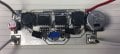
I built a circuit based on "Increasing Available Load Power in an LM2587 Boost Regulator" app note (its link is http://www.ti.com/lit/an/snva552/snva552.pdf). The difference is my input is around 24VDC, the output I want is 28VDC. So at output the resistors value are changed to get 28VDC out.

The circuit is working fine when there is no load at all! The output is 28VDC, and switch the circuit ON/OFF, everything is working fine.

But when putting a load drawing current 1A, the circuit input voltage drops and the circuit is not working.

If I switched ON the circuit without load, then connected the 1A load afterwards, the circuit is working fine and the output is drawing 1A. But if I switch OFF the circuit and then switched it ON (a load still connected), then the circuit failed. Any thoughts please?

Thanks in advance.
 

Thread Starter

Jackjin1981

Joined Oct 2, 2017
8


The only difference is the two resistors at FB pin. The resistors I used is 56.2k ohms and 2.54k ohms. The output I want is around 28.4V DC.
 

AlbertHall

Joined Jun 4, 2014
12,625
It should be Input, not output.
I am using a power supply to provide 24V DC as input. When the load is connected, then switched ON the circuit, the input voltage is showing 3.5V instead of 24V.
Then it sounds like your 24V power supply cannot supply sufficient current to cope with the current the booster draws when it is powered up and the power supply current limit trips.
 

Thread Starter

Jackjin1981

Joined Oct 2, 2017
8
Then it sounds like your 24V power supply cannot supply sufficient current to cope with the current the booster draws when it is powered up and the power supply current limit trips.
i have tuned the power supply current supply to maximum 3A, but still failing.
 

Thread Starter

Jackjin1981

Joined Oct 2, 2017
8
Then it sounds like your 24V power supply cannot supply sufficient current to cope with the current the booster draws when it is powered up and the power supply current limit trips.
Can I use some Inrush current limiter to fix this problem? where shall I put?
 

Picbuster

Joined Dec 2, 2013
1,058


The only difference is the two resistors at FB pin. The resistors I used is 56.2k ohms and 2.54k ohms. The output I want is around 28.4V DC.
I do not understand why the left hand Fb pin is connected to GND. This will order the LM to Jack up the output voltage.
Try to remove the left hand LM and try again.

Picbuster
 

Thread Starter

Jackjin1981

Joined Oct 2, 2017
8
I do not understand why the left hand Fb pin is connected to GND. This will order the LM to Jack up the output voltage.
Try to remove the left hand LM and try again.

Picbuster
According that app note, the right-hand side regulator is the master one that sets the duty cycle of both regulators.
I used two LM2587 just in order to get more current output power
 

dendad

Joined Feb 20, 2016
4,637
It could be something like the switching noise getting into your input supply. Have you tried a large low ESR electrolytic cap on the regulator input?
 
Top