 Facebook
 Google
 GitHub
 Linkedin
Hi all,
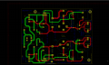
I've just drawn a simple circuit with LM2576t Adjustable Switcher.
I'd want to get a versatile psu, 3A , from 1.3 to 15 V.
I'm in doubt about proper wiring of trimmer - see pink ovals - bourns 50 K 24 turns.
Could you check the entire board also, in order to avoid wasting money ....... ?
As usual, thanks a lot.
Jm
Attachments
-
 243.4 KB Views: 9
 -
 210.8 KB Views: 8
 -
124 KB Views: 2
-
 247.5 KB Views: 8
 -
114.8 KB Views: 0


