linear amplifier

Thread Starter

praondevou

Joined Jul 9, 2011
2,942
I want to amplify an AC signal 100Hz 10Vpp to 60Vpp. Small component count and low input offset voltage (less than 1mV) are desirable. Output current has to be at least 200mApp.

I've seen Opamps from APEX, but they cost more than $120. Is there a cheaper option? Building a circuit from zero will take too much time.

Thanks
 

Audioguru

Joined Dec 20, 2007
11,248
An LM3886 50W audio amplifier IC with a plus and minus 35V supply or a single +70V supply can easily produce 60Vpp into any load from 8 ohms to infinity.
Two resistors set its gain but a gain of 6000 at 100Hz might need an additional cheap opamp as a preamp.

Your requirement of the very low offset voltage will need trimming.

It costs only $6.72US each at Digikey today. They have 4183 of them in stock today and can get 40,260 more in a couple of days.
 

Thread Starter

praondevou

Joined Jul 9, 2011
2,942
Ok, the audio amplifiers is something I can have a look at.

However, this circuit is used to demagnetize/magnetize iron core toroids with a controlled waveform inside a Helmholtz coil. So an offset is really not useful.

Maybe more important than a low offset is a low offset voltage drift. Once adjusted it had to be stable.

Thanks all.
 

Thread Starter

praondevou

Joined Jul 9, 2011
2,942
Why do you need low input offset if the signal is AC? Just AC couple the output if you want zero offset.
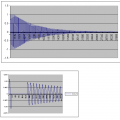
The load is a coil. The input is a sinewave that looks like this:

There is an interruption somewhere in between. Vpp max is 10V. Vpp min is 1mV (1:10000).
 

Attachments

kubeek

Joined Sep 20, 2005
5,796
You could build a discrete audio-type amplifier, because +/-60V is getting a bit too much for integrated solutions. Because the current is so low, a capacitor in series should help with any offset that might be present, or you can make a DC servo amplifier to null the offset automatically.
 

Thread Starter

praondevou

Joined Jul 9, 2011
2,942
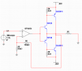
Why does this configuration oscillate?


It starts oscillating with increased load (without a load/ a small load it works perfectly up to 20kHz square wave). However with a 20Ohm load it starts oscillating at a very high frequency (some MHz as far as I remember) even with a 100mHz sine wave. Obviously there is some undesired phase shift, adding caps in the feedback loop only worsens the problem.

http://www.ti.com/lit/ds/symlink/opa454.pdf
http://www.onsemi.com/pub_link/Collateral/D44H-D.PDF
http://www.onsemi.com/pub_link/Collateral/TIP29B-D.PDF

Adding base resistors or base-emitter resistors to the TIPs doesn't make a difference for the oscillation issue.

A simple npn/pnp at the output does work, but I want more amps therefore the darlingtons.
 

Attachments

Ron H

Joined Apr 14, 2005
7,063
Why does this configuration oscillate?


It starts oscillating with increased load (without a load/ a small load it works perfectly up to 20kHz square wave). However with a 20Ohm load it starts oscillating at a very high frequency (some MHz as far as I remember) even with a 100mHz sine wave. Obviously there is some undesired phase shift, adding caps in the feedback loop only worsens the problem.

http://www.ti.com/lit/ds/symlink/opa454.pdf
http://www.onsemi.com/pub_link/Collateral/D44H-D.PDF
http://www.onsemi.com/pub_link/Collateral/TIP29B-D.PDF

Adding base resistors or base-emitter resistors to the TIPs doesn't make a difference for the oscillation issue.

A simple npn/pnp at the output does work, but I want more amps therefore the darlingtons.
With no load, the TIPs don't draw enough current to turn on the D44/D45 parts, so the TIPs just act as emitter followers. With load, the Sziklai pairs are active, and are feedback loops. If both transistors in a Sziklai pair have Ft's that are around same order of magnitude, they may oscillate, independent of the circuit driving them.
Try decreasing the 2k resistors to around 100Ω and see if that helps with the oscillations. Note that the D44H11 and D45H11 will not begin to turn on until load current exceeds about 6mA.

I don't see why you don't just use the D44H11 and D45H11 as emitter followers. They have minimum betas of 60, and the op amp can put out ±50mA. That should reliably drive out ±1 Amp.

Or, as others have said, use an audio amp with series capacitors to eliminate the offset.
 
Last edited:

Thread Starter

praondevou

Joined Jul 9, 2011
2,942
I don't see why you don't just use the D44H11 and D45H11 as emitter followers. They have minimum betas of 60, and the op amp can put out ±50mA. That should reliably drive out ±1 Amp.
My mistake. I should have started a new thread. It's the same signal but for a different application. Now current will be up to 4A at +-40V.

That's why I thought using the darlingtons is a good idea.
 

Audioguru

Joined Dec 20, 2007
11,248
The transistors are not biased so they cause severe crossover distortion which probably triggers the oscillation. Bias the transistors properly then maybe they won't oscillate.
 

Thread Starter

praondevou

Joined Jul 9, 2011
2,942
The transistors are not biased so they cause severe crossover distortion which probably triggers the oscillation. Bias the transistors properly then maybe they won't oscillate.
Why do they not cause any crossover distortion at lower input signal amplitudes and/or higher load resistance?
 

Thread Starter

praondevou

Joined Jul 9, 2011
2,942
Hum, I'm gonna implement your recommendations tomorrow.

I went down to 100 mHz(!) and it still oscillates, not starting at zero crossing. On a sinewave it starts at a certain voltage level with maximum amplitude (superimposed on the sinewave) and then decreases when the voltage goes towards zero...

If I'm not getting it to work tomorrow I'll post some oscillographs.

Thanks all
 

Thread Starter

praondevou

Joined Jul 9, 2011
2,942
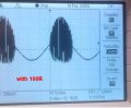
Lower resistances from emitter to base (100R) made things worse.
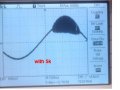
The oscillation starts when reaching a certain voltage level, at about 600mV at the base of the D44/45H11s, so apparently when they start to conduct. The oscillation occurs on both sides, below is showing only one side with a small input signal.

It does work without oscillating when I put 1nF caps from base of the D44 and base of the D45 to their collectors.

Thanks


Attachments

Top