Linear actuators synchronized

Thread Starter

Rob456

Joined Dec 16, 2024
4
Hi this is my first post and I’m a newbie with electronics.
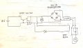
I’ve ordered two linear actuators for a project and noticed they have different speeds. I expected some difference but it is quite a lot. That’s why I ordered a PWM to adjust the speed of the fastest actuator. For one direction this works. But when I change the direction with the DPDT switch, the actuator with the PWM does nothing.
Could you help me check the circuit I intent to test? I plan to use a diode bridge after the DPDT switch to keep the polarity constant before the PWM. However when the direction of the actuator is reversed, I want to use a DPDT relay to automatically change the polarity after the PWM. I plan to do this with a rectifier/diode to only trigger the relay when the polarity is swapped.
Do you think this will work? And what type of diode should I use?
Thanks in advance!
 

Attachments

sghioto

Joined Dec 31, 2017
8,633
Looks like it should work.
Have you tried the pwm in both directions on that one actuator?
Any 1N4000 series diode is fine.
 
Last edited:

Thread Starter

Rob456

Joined Dec 16, 2024
4
Looks like it should work.
Have you tried the pwm in both directions on that one actuator?
Any 1N4000 series diode is fine.
Thanks for the quick reply. Yes I’ve tried both directions on the same actuator but it only works when I change the connections on the output side of the PWM. Changing polarity before the PWM made the actuator not responsive at all. That’s when I found out that a PWM cannot go negative apparently..
 

LowQCab

Joined Nov 6, 2012
5,101
Having actuators that run at different speeds is going to be problematic no matter what You do,
( that's guessing that they are both operating the same device ).

More information will get You more appropriate solutions.

Every individual actuator will have a slightly different speed, unless they are powered by Stepper-Motors.

If your Actuators have very noticeable speed differences,
send them back and get a matched-pair,
because a PWM-Motor-Speed-Controller is NOT going to be a satisfactory solution.
.
.
.
 

MisterBill2

Joined Jan 23, 2018
27,159
There are ways to force actuators to run in "lockstep", and usually they do not involve PWM drivers. And although the concept is "sort of simple" the actual implementation is usually not simple.
What sort of linear actuators are these? I am guessing that they have brush type DC motors. If the motors have shaft encoders then synchronizing them can be done without any problems. And it can get easier with a simple processor.
 

Thread Starter

Rob456

Joined Dec 16, 2024
4
They think you are right about the brush motor. Maybe good to know; these are long stroke (1200mm) actuators so perhaps the speed difference is not that big but due to the long distance it becomes very evident that they perform differently. The application is lifting a panel vertically to reveal a hidden TV. If the speed difference is too big, the panel will be tilted and distort the cabinet it is connected to.
 

LowQCab

Joined Nov 6, 2012
5,101
First,
use 2, or 4, very long, Ball-Bearing-Drawer-Slides to insure that the Panel will always move precisely, and repeatably.

Second,
use one Actuator in the center, with a pivoting attachment on each end,
that does nothing except provide vertical motion.

Third,
Supply us with as much information as possible on the Actuators that You have, including pictures.
The Electrical configuration is the most important part.
.
.
.
 

MisterBill2

Joined Jan 23, 2018
27,159
First,
use 2, or 4, very long, Ball-Bearing-Drawer-Slides to insure that the Panel will always move precisely, and repeatably.

Second,
use one Actuator in the center, with a pivoting attachment on each end,
that does nothing except provide vertical motion.

Third,
Supply us with as much information as possible on the Actuators that You have, including pictures.
The Electrical configuration is the most important part.
.
.
.
If an encoder can be part of each motor drive, then the logic to slow a motor until the other catches up is fairly simple. That could also be implemented using "string pot" position sensors for each Linear Actuator. That might be even simpler.
 

ronsimpson

Joined Oct 7, 2019
4,645
When I was a kid, we installed pivot aeration systems on the farm. The system walks around the field in a circle. The outside tower runs as fast as it can. The next tower needs to run about 5% slower. Each tower must be slower. Each tower watches to see if it is ahead or behind. A simple cable and two switches cause 12 towers to walk together round a circle. If farmers can make 12 motors track we can make two actuators track.
1734453833652.png
 

MisterBill2

Joined Jan 23, 2018
27,159
Certainly it can be done, but is it worth the Time and Money ?
.
.
.
For an agricultural watering system the answer is "totally worth the effort, worth both the time and the money. " The irrigation system components that would be damaged cost quite a bit, and the water pumped from the deep wells is expensive if you count the cost of the electricity to pump it out. And the crop damage if the pivot system damages crops by malfunction adds up fast.
 

MisterBill2

Joined Jan 23, 2018
27,159
For raising and lowering a panel, or a large TV, a variation of the string/spool scheme with a differential in between to momentarily slow the faster motor will work. And really, the sensor can just be a switch that is operated by one side getting ahead of the other. The basic challenge is being able to monitor the difference in motions of the two actuators.
Is this system built already? Or is it built and now in the de-bugging mode??

An experiment could be to put the two motors in series, which would force the current to be the same. That might reduce the problem. It might even be a solution..

The challenge is that for any feedback system, there must be a feedback signal of the variable to be controlled. With motor driven linear actuators it may be possible to add a sensor to monitor motor speed or revolutions, or monitor the linear movement of the axis.. One radical option would be to exchange the motors for stepper motors , which are simple to keep in step.
 
Last edited:

ronsimpson

Joined Oct 7, 2019
4,645
For raising and lowering a panel, or a large TV
For the large TV project I would use a tilt switch for feedback.

I use linear motors in parallel and they run just fine because, the faster motor picks up most of the load, which slows it down.
I don't really know what this project is, but I think some mechanical work would solve the problem.
 

MisterBill2

Joined Jan 23, 2018
27,159
It has been two weeks. Did the TS give up on us? Or find a way to make it work?If the motors vary their speed with the load effort then some sort of sensor scheme is required. Either to adjust the speed, or to force the motors to run in lock-step. There are some simple schemes for that possible.
 

Thread Starter

Rob456

Joined Dec 16, 2024
4
Thank you for all your tips and knowledge! I’ve been ordering and testing some of the suggestions past weeks. Here’s an update:
I tried the circuit from my first post - it worked to control the speed of one actuator using the PWM and to change direction on both. However, I think some of the components cause a too high resistance for the speed controlled actuator as its max speed was now slower than the previously slower actuator. After that I tried the sliders which LowQCap to guide the panel. Then I just connected both actuators in parallel with the DPDT switch but without the PWM etc. and attached them to the panel (in the panel’s plane). I assumed the fastest actuator would be taking most of the load, allowing the slower one to pick up and support (and for the way down, the fastest one would pull the slower one down with it). It seems to work, though with some noise. I think it’s nothing crazy for actuators under load but I just wanted to check with you guys if pulling the slower actuator upwards is damaging for the actuators. I know putting load toward the motor should not be damaging (main function of the actuator) but actively pulling it I am not sure about.
The picture shows the current status (still needs a paint job)
 

Attachments

Top