Level of voltage swing on +ve lead of electret mic

Thread Starter

Willen

Joined Nov 13, 2015
334
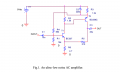
Trying the preamp, uploaded below. I have modified another same circuit with common value of resistor and 7Vcc. I am using LT Spice for the modification. I made the output swing of 400mV p-p AC with 8mV input AC source, It's the simulation of electret mic. Thus input sine from of 2mV to 8mV gives me better sine output. But with 10mV input gives me little clipping or little unusual sine output.

So if anyone had measured the voltage swing on the possitive lead of such electret capsule, please tell me so I will set same level of sine source as mic in simulation.
EDIT: My real work has been uploaded in .asc file.
 

Attachments

Last edited:

Thread Starter

Willen

Joined Nov 13, 2015
334
hi W,
I do not see any clipping of the output, using a 30mV source signal, check your results.
E
Hi,
Hm... I think I made some mistake.
Recently I have noted that just single transistor preamp with 5V give me more than 350mV p-p sine output. Now a days I am using same type of single transistor preamp for computer recording. The output level is not enough (around 350mV according to simulation) so I have to fade up the computer's mic input volume button which also increased hiss noises of my poor PC's internal noise (maybe from its A to D converter. So I want to get more output level so I do not need to fade up the computer mic volume button.

This two transistor preamp giving me same low output as currently I am using. Can I get better out with some tweak?
 

ericgibbs

Joined Jan 29, 2010
21,396
hi,
OK, try a 2.2uF capacitor across the 22R emitter resistor of the first transistor.
The LTS sims look OK.
Let us know the result.E
 

Thread Starter

Willen

Joined Nov 13, 2015
334
It's funny! I spent hours in LTspice to change different values of resistors to get higher output but was failed. Your simple suggestion of adding 2.2uF cap worked amazingly!

Somewhere I had read the output point should swing around half of the supply voltage for better result. Output point here is the Collector of Q2 but its voltage swing (after aadding bypass cap of 2.2uF in the Emitter of Q1) is just 1.1V to 2.4 p-p. But the Supply is 7.4V. Don't we need to set it to around 3.7V ?

Hi Dick, I will see if I can understand the mic specification clearly. Thank you!
 

ericgibbs

Joined Jan 29, 2010
21,396
hi W,
It is not necessary to get the Collector quiescent voltage at Vsup/2 for such a low level amplifier, providing it gives the gain you require.
It is important that the upper swing of the signal does not approach Vsupp and the lower swing does not approach the Vsat.

The 2.2uF will raise the higher end frequencies response, but I would say it will acceptable.

E
 

Thread Starter

Willen

Joined Nov 13, 2015
334
The 2.2uF will raise the higher end frequencies response, but I would say it will acceptable.

E
Then maybe adding a 100pf ceramic disc in across base-emitter of Q1 would ground unnecessary high frequencies, higher than audio?
 

ericgibbs

Joined Jan 29, 2010
21,396
hi,
What would you say are the unnecessary high frequencies.?
If you start changing to many components you will degrade the signal quality, does it sound distorted.??
 

DickCappels

Joined Aug 21, 2008
10,661
After a little more reading, it looks like the short answer to your original question is: A few millivolts when speaking directly into the microphone.
 

Thread Starter

Willen

Joined Nov 13, 2015
334
Hi Dick, Few milivolt mean I think maximum won't go higher than 10mV. So I designed with 5mV source.

Hi Eric, When I added 2.2uF bypass capacitor as gain booster, then I got some clipping in output with around 10mV input. So changed many resistors and made new modification. Now its output seems fine from starting level to 10mV. (I wish mic won't produce more than 10mV audio). Please check it once.
 

Attachments

Thread Starter

Willen

Joined Nov 13, 2015
334
Update: Wow! I prepared the preamp and got amazing result, just in ear (don't know about in theory performance)! I got more than satisfying level of output. I had to Fade Out the volume buttom of PC to just 1 (out of 100). Still it was loud. So I decided to add a pot at the end as volume control. Because of analog audio amplify, hiss has been overlap by real audio! Pretty clear and good voice I've ever got in my practice.

Supply was 8V and mic feed resistor was 10k. It was picking audios from outside of my room too, so maybe I need to increase the feeder resistor around 15k to decrease the gain of mic. (I have OpAmp too but I feel happy to play with transistors).
 
Last edited:

Thread Starter

Willen

Joined Nov 13, 2015
334
hi W,
When you are ready, please post your asc file, I would like to try it and keep it on file.
E
Hi eric,
There's exact file uploaded in #15. I used pretty cheap 5mm electret mic, scrapped from $1 Chinese earpiece. It sounds pretty nice in my earpiece. :)
 
Last edited:

Thread Starter

Willen

Joined Nov 13, 2015
334
Hi again,
As I seen, there are 100nF capacitor as electret mic to base (of transistor) coupling capacitor. But some of the circuit has 10uF electrolytic. The preamp I worked had 10uF too, then I decrease down to 2.2uF. What's the effect if I used 100nF there and again 10uF?
 

ericgibbs

Joined Jan 29, 2010
21,396
hi Willen,
To show the effect of the different caps, I will run a LTSpice sim showing the change in amplifier bandwidth.
Post it later.
Eric

EDIT:
Two sims
0.1uF thru 1uF in 0.1uF steps
&
1uF thru 10uF in 1uF steps

Note the increase in low frequency bandwidth as the caps get higher in vale.
 

Attachments

Last edited:
Top