Facebook
 Google
 GitHub
 Linkedin
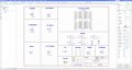
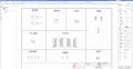
Dear all, hope you are doing great. I am designing a circuit using EasyEDA simulation tool. But I am facing a problem after connecting the relay to the single-Chip IC (STM32 103RTC6). The low voltage is showing around 2V, whereas it was originally supposed to be 0 volts. I am still unable to understand why it is, so I need your help, please.
Low Voltage level problem in STM32 system chip
- Thread starter Mike2526
- Start date