Let's talk about fence Chargers.

Tonyr1084

Joined Sep 24, 2015
9,744
Don't the new ignition modules use a dual polarity spark? I mean one spark (lets call it a positive current spark) then a second spark of reversed current. The thinking (I think) is to prolong the lifespan of a spark plug. If current is always flowing in one direction it carries bit by bit electrode material and deposit it on the ground probe. So they reverse the direction of the spark to reduce the amount of spark plug degradation and give the cylinder two sparks per combustion process; which also helps ignite the fuel making it even more efficient.
 

Blank_Stare

Joined Jul 29, 2017
44
Coil on plug is the new norm now. Each cylinder has its own coil placed directly above the spark plug opening and connected with a short section of high tension wiring encased in a rubber type boot for sealing and insulation. Very effective and low breakdown. Waste spark is old school now for the most part.
Whew - I am much relieved. LOL!! :p
 

debe

Joined Sep 21, 2010
1,419
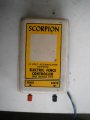
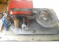
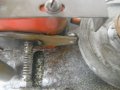
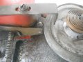
This is a fairly old 12V dc electric fence unit I found in a scrap yard. Its pretty basic using points on a disc that swings back & forth. All it needed was the points needed cleaning, & this thing gives a fairly vicious spark.SCORP ELECT FENCE.1.JPG SCORP ELECT FENCE.3.JPG SCORP ELECT FENCE.4.JPG SCORP ELECT FENCE.5.JPG
 

RichardO

Joined May 4, 2013
2,270
This is a fairly old 12V dc electric fence unit I found in a scrap yard. Its pretty basic using points on a disc that swings back & forth. All it needed was the points needed cleaning, & this thing gives a fairly vicious spark.View attachment 131986 View attachment 131987 View attachment 131988 View attachment 131989
I had one like this as a kid. What is not apparent in your photo's is that the step up transformer is what moves drives the rotating contact.
The sequence is this:
The transformer is energized by the contacts closing. This attracts the transformer's movable pole-piece opening the contacts. The moving pole-piece causes the disk to wind up its spring. Once the spring is wound the disk reverses direction and closes the contact.

The time it takes to cycle is determined by the tension on the spring.

A truly beautiful design where nothing is wasted.
 

Blank_Stare

Joined Jul 29, 2017
44
I had one like this as a kid. What is not apparent in your photo's is that the step up transformer is what moves drives the rotating contact.
The sequence is this:
The transformer is energized by the contacts closing. This attracts the transformer's movable pole-piece opening the contacts. The moving pole-piece causes the disk to wind up its spring. Once the spring is wound the disk reverses direction and closes the contact.

The time it takes to cycle is determined by the tension on the spring.

A truly beautiful design where nothing is wasted.
Nothing but battery power, right? If I understand correctly, this is an "always on" mechanical device, that does not get triggered by closing the circuit between ground and the positive lead, like modern chargers do. This thing just runs 24/4, winding up and releasing, right?

If I am wrong, please educate me - Sometimes I am a slow learner. I was under the impression that the ones on the market now more or less use flesh as the switch to send power, and until the circuit is completed, they are more or less on standby? I know it's not quite that simple, but isn't that the gist of it?
 
Last edited:

crutschow

Joined Mar 14, 2008
38,578
If I understand correctly, this is an "always on" mechanical device, that does not get triggered by closing the circuit between ground and the positive lead, like modern chargers do. This thing just runs 24/4, winding up and releasing, right?
It's not "always on" as it only conducts current for the few ms that the contact on the wheel meets the stationary spring-loaded contact.
The momentary surge of current through the transformer also attracts the spring-loaded contact which gives a backward kick to the moving contact on the wheel, winding it up for the next cycle.
The opening of the contact generates an inductive kick in the transformer, similar to a car coil, which generates the spark to the fence.
 

Blank_Stare

Joined Jul 29, 2017
44
It's not "always on" as it only conducts current for the few ms that the contact on the wheel meets the stationary spring-loaded contact.
The momentary surge of current through the transformer also attracts the spring-loaded contact which gives a backward kick to the moving contact on the wheel, winding it up for the next cycle.
The opening of the contact generates an inductive kick in the transformer, similar to a car coil, which generates the spark to the fence.
Wait, isn't the wheel always using power, and always in motion? I get that the current doesn't always flow, but that does not mean that the device isn't using power from the battery to move the wheel, right?

Or does triggering a spark activate the wheel to reset, with no mechanical action between reset, and triggering the spark?

I love the old tech, too. It's often amazing the simple solutions that practical people came up with, to solve seemingly difficult puzzles.
 

crutschow

Joined Mar 14, 2008
38,578
Wait, isn't the wheel always using power, and always in motion?
It always in motion, but it's like the balance wheel in a watch that oscillates with a kick every period from the escapement.
Here the wheel is an oscillator consisting of the inertia of the wheel and the coil spring constant.
Even if you removed the power the wheel would likely continue to oscillate for several times just due to the wheel spring and the fixed contact spring.
I get that the current doesn't always flow, but that does not mean that the device isn't using power from the battery to move the wheel, right?
How can it use power if no current is flowing?
Power is volts x amps.
No amps, no power.
 

Blank_Stare

Joined Jul 29, 2017
44
It always in motion, but it's like the balance wheel in a watch that oscillates with a kick every period from the escapement.
Here the wheel is an oscillator consisting of the inertia of the wheel and the coil spring constant.
Even if you removed the power the wheel would likely continue to oscillate for several times just due to the wheel spring and the fixed contact spring.
How can it use power if no current is flowing?
Power is volts x amps.
No amps, no power.
OK, so it oscillates a few times....then it needs some power to make it keep oscillating, right? Even if it only needs a kick in the pants every few seconds, it uses power to keep that wheel moving, doesn't it?

I get that the fence isn't drawing power while on standby, but the "watch" needs something to keep it in motion, right?
 

debe

Joined Sep 21, 2010
1,419
Crutschow has described the workings perfectly. The orange block is the HV transformer also acting as a solenoid to kick the balance wheel.
 

Blank_Stare

Joined Jul 29, 2017
44
Crutschow has described the workings perfectly. The orange block is the HV transformer also acting as a solenoid to kick the balance wheel.
Sooo... let me see if I can wrap my pea-brain around this...

The battery spins the wheel, and charges the capacitor, and when the spring is tight, and the system is charged, the unit stops drawing energy, and the wheel goes motionless. Then, when the capacitor is discharged (because the fence got activated), the wheel spins, and everything goes back into motion?

Lather, rinse, repeat?...
 

debe

Joined Sep 21, 2010
1,419
The capacitor is across the points to reduce arcing on the points & tuning the coil just like automotive ignition system.
 

crutschow

Joined Mar 14, 2008
38,578
The battery spins the wheel, and charges the capacitor, and when the spring is tight, and the system is charged, the unit stops drawing energy, and the wheel goes motionless. Then, when the capacitor is discharged (because the fence got activated), the wheel spins, and everything goes back into motion?
Sorry, that's not at all how it works. :(
Have you really read my explanation?
I will give it another try. :rolleyes:

The short instant the contacts make contact is the only time power is drawn from the battery.
(Why does that seem so difficult for you to understand?)
During the rest of the time the wheel is freely oscillating.
The only energy during this time is that which is being transferred from the wheel inertia to the coil spring and then back from the spring to the wheel inertia. This involves no electrical energy.

When momentary contact is made, two things happen:
  1. Current flows through the primary of the transformer and inductive energy is stored for the subsequent HV generation.
  2. The transformer acts like a solenoid which attracts the fixed contact against its spring, giving a kick to the wheel, transferring inertial energy to it, and breaking the contact.
The breaking of the contact is what generates the HV.
The inductive energy of the current flowing in the coil primary tries to keep the current moving, but when the contacts open, it suddenly has nowhere to go, other than the capacitor connected across the points (without the capacitor all the inductive energy would be dissipated in an arc across the opening points).
This pulse of current into the capacitor causes a momentary high voltage in the capacitor and thus across the coil primary.
This pulse of voltage is increased by the many turns in the transformer secondary, which is the pulsed HV output to the fence.

Does all that make sense to you?
 

#12

Joined Nov 30, 2010
18,224
That might be what I saw in 1959. I had the intellect to understand it as a mechanical oscillator and a spark coil, but the mental photograph has disappeared from inside my head.:(

The memory of testing it with a piece of grass has not.:D
 

Thread Starter

Wendy

Joined Mar 24, 2008
23,797
Thank you I found the mechanical methods fascinating. Still drawing the transistor only version just taking longer than I expected Then I will do a few 555 versions

I've been thinking abot ignition col vs a conventional transformer . I think the ignition coil may be in the borderline dangerous catigoy due to the extreme voltages generated. If you have several miles of electric fence it may be needed, but for a small pen. it is overkill. Speaking to @Blank_Stare My design goal is to keep the current draw low enough to allow a simple solar charger to keep a SLA (sealed lead acdt battery topped off(more on this later)witt both the charger and the FC connected to the battery at the same time.
 
Last edited:

crutschow

Joined Mar 14, 2008
38,578
I think the ignition coil may be in the borderline dangerous catigoydue to the extreme voltages generated.
You can reduce the output voltage by reducing the input voltage in a capacitor discharge design, or reducing the primary current in an inductive (Kettering) design.

But shocks from ignition coils are generally not considered life threatening because of the low current (although they hurt like heck :eek:).
It's the current that kills.
 
Top