LED Turns on In Specified Voltage Range

Thread Starter

Kayto99

Joined Feb 26, 2023
11
I'm looking to get some help in designing a board that takes an input voltage and confirms if the that voltage resides between V = 27.5V and V = 29.5V without an external power source. When the input voltage is between this range I would like an LED to light up. So far I've been exploring using TL431s as an attempt to create this voltage window.

1712730942076.png

I've split the circuit into two for lower and upper limits I would like to achieve.
The first I believe should switch on the resistor when the voltage at Vref of the TL431 = 2.5V, which should be the case from the voltage divider at Vin = 27.5V.
The second therefore is incorrect and instead of switching it on at 29.5V I would like to shut it off when it reaches that value or shortly after exceeding it.

How could I achieve turning off the LED in the second circuit and how would I go about combining the two to make the LED turn on only when Vin is in the range of 27.5V-29.5V?
 

Attachments

Thread Starter

Kayto99

Joined Feb 26, 2023
11
Ah you're right. It was a problem with my lib file. I'm now able to recreate what yours was showing initially. Thank you for the help!
 

ericgibbs

Joined Jan 29, 2010
19,194
Hi
I assume some of us know that a BJT can be used in reverse voltage mode?
The Gain is reduced, but they will work in reverse.
I believe the TS intended to connect the transistors using this option?

Perhaps he can confirm this?
E
 

Thread Starter

Kayto99

Joined Feb 26, 2023
11
I translated the schematic with the first schematic that worked on the simulation but it seems to light up when I put around 10V in:1712937626826.png


Going to try the schematic that eetech created and see if I have better luck
 

eetech00

Joined Jun 8, 2013
4,061
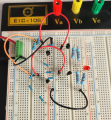
When trying this on a breadboard it seems that I can only get the right side of the circuit to work. It turns on around 27.2V but has no shut off for the higher voltage. If I try to use the left side of the circuit R1, R2, U1 the LED remains off the whole time.
Pleas post a good photo of breadboard
 

eetech00

Joined Jun 8, 2013
4,061
When trying this on a breadboard it seems that I can only get the right side of the circuit to work. It turns on around 27.2V but has no shut off for the higher voltage. If I try to use the left side of the circuit R1, R2, U1 the LED remains off the whole time.
I have this circuit on the bench.

change R7 from 2k to 2.4k

The "on" LED response is not snappy. That is, the LED begins to glow at about 28.0 volts, and "snaps" off at 29.5 volts.
On voltage can be adjusted with a little divider tuning. However, I don't think there is much that can be done for 'on' voltage hysteresis without significantly increasing circuit complexity. I think it will be better to use 2-LM339 (one chip) in a window comparator with hysteresis configuration. This will provide accurate and "snappy" thresholds.
 

crutschow

Joined Mar 14, 2008
34,933
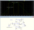
Below is the LTspice sim of an LM339 (quad), or LM393(dual) window comparator circuit, as suggested by eetech00:
The LED (yellow trace) is on when the voltage (green trace) is between 27.5V and 29.5V.

1713119551229.png
 
Last edited:

Thread Starter

Kayto99

Joined Feb 26, 2023
11
Sorry for the delay. Back at the bench now. I tried with 2.4k on the series resistor for the LED. Still no luck.
20240415_115734.jpg

No luck when the anode from D1 is connected to the Ref of D2, when I remove this the LED turns on at 27.2V as shown below:
20240415_115743.jpg
Tried to make it as clear as possible in the picture!
 
Top