LED strip

Thread Starter

scam313

Joined Jul 19, 2022
44
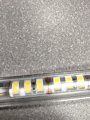
In a refrigerator lighting tube they have an LED strip that has 90 LEDs with 3 per segment and a resistor every segment.The LEDs are in parallel running at about 850mA, it seems that the resistor is just a jumper to close the segment of the circuit. Schematic wise would it be 3 LEDs in parallel then the resistor in parallel with 12VDC jumping to each segment and sharing a common ground?
 

SamR

Joined Mar 19, 2019
5,488
LEDs in a series will be a problem when one burns out. Which is why paralleling them helps to prevent an entire string going out when a single series LED fails. Not to mention the voltage drop problem in series.
 

MisterBill2

Joined Jan 23, 2018
27,514
The primary advantage of 3 LEDs in series with a single resistor is a more convenient supply voltage, the second advantage is less power wasted in resistors, the third advantage is better use of space because of fewer resistors. Aside from that, it usually makes the power supply design a bit more efficient and less expensive. It also tends to make the brightness more uniform. Those are the main reasons for the series arrangement of LEDs.
 

WBahn

Joined Mar 31, 2012
32,829
This is the type of design but 3 LEDs with a resistor that I believe is a jumper to close the segment. The power supply is a pcb with a rectifier to take the 110v AC to 12vdc
I can't quite make out the wiring of the strip in the vicinity of the resistor. But I can tell you that the resistor is NOT being used as "a jumper".

A better picture of the strip would be helpful. Do you actually have any of these on hand?
 

MisterBill2

Joined Jan 23, 2018
27,514
The resistor is still serving to complete the circuit, although the term "jumper" tends to imply zero resistance, The resistor IS a SERIES element of this circuit no matter where in the sequence it is, and the current limiting function is the same.
 

MisterBill2

Joined Jan 23, 2018
27,514
Here is a picture, it says 271 on the resistor
271 is the code for 27 x 10 ohms, meaning 270 ohms. That is a reasonable value to drop the voltage from 12 volts to whatever three white LEDs in series require. if the forward voltage at the rated current is 2.7 volts, ( a reasonable guess), then 3 in series will require 8.4 volts, with 3.6 volts dropped across the 270 ohm resistor

The references to series and parallel made in the link in post #9 are about strips of LEDs, not individual devices. And really, the statements made in that link seem a bit off as far as accuracy goes.
 

sghioto

Joined Dec 31, 2017
8,634
A 270 ohm resistor for each segment doesn't add up from the numbers listed in post #1 though.
Assuming 3.6 volts across the resistor the current through each segment is 13.3ma and that times 30 segments is 399ma not 850ma. If it's actually 850ma then 850/30 = 28.3ma per segment.
28.3 times 270 = 7.64 volt drop across the resistor.
 

MisterBill2

Joined Jan 23, 2018
27,514
The fact is that we are not told the actual voltage across each LED, nor has the TS verified that the voltage is actually 12 volts. The refrigeration application strips that I have use 24 volts. At least that is what the "ballast" device that they were connected to has on it's label.
12 volts was mentioned in post #2, not by the TS.
A different set of LEDs in an outside winter display did have a few series strings running directly on the bridge-rectified 120 volt mains. There were about 28 individual bulbs containing LEDs in each series section. Those series sections started illuminating with about 60 volts across them, but did not increase brightness as the voltage applied to the diode bridge was raised from 75 volts to 120 volts.
 
Top