LED SoC indicator circuit help

Thread Starter

Sijia Wu

Joined Jul 22, 2015
23
Hi all,

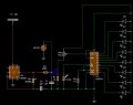
I am building a SoC LED indicator for my 48V battery with 8 LEDs, which displays the pattern when the battery is about 7/8 charged:
output_Vm89Y5.gif
I am using LM3914 to measure the voltage, and I was thinking maybe I could use the 555 to convert DC to triangular wave like this to get the pattern. The conversion sort of works on everycircuit, but not in Circuit Wizard when I connect the triangular wave output to the input of the LM3914 circuit: both parts of the circuit work individually, but not when they are connected. The weirdest thing is, when two parts are separated, I'm getting a good shape and the output of the 555 part of circuit has a peak of ~38V (range:10-38V) as shown in the picture "P, not connected", which is desired. However when I connect them, the output from the same point gets 100 times smaller, with the peak being several hundred mV as shown in the picture "P, connected", which is the obvious reason why none of the LEDs would light up. I would really like to know why as this makes no sense to me at all.

I know it's very wrong to use such large voltages as it will burn everything in real life, but I'm planning on looking at the voltages after I figure this little problem out...

Thanks in advance!!
 

Attachments

djsfantasi

Joined Apr 11, 2010
9,156
The 4017 and a few diodes can display a back and forth sequence on 5 lights. If you have more, you need to daisy chain the 4017s so you have at least (two times the number of LEDs) outputs.
 

Thread Starter

Sijia Wu

Joined Jul 22, 2015
23
The 4017 and a few diodes can display a back and forth sequence on 5 lights. If you have more, you need to daisy chain the 4017s so you have at least (two times the number of LEDs) outputs.
Ah I see... is the number of lights in the sequence a dependent of the voltage?
 

MikeML

Joined Oct 2, 2009
5,444
A led SOC charge indicator is nothing but a (not-very-good) voltmeter. Why not just use a voltmeter?

btw- estimating SOC from a battery's terminal voltage does not work very well.
 

djsfantasi

Joined Apr 11, 2010
9,156
Ah I see... is the number of lights in the sequence a dependent of the voltage?
No, not at all. The number of lights in a sequence is dependent on your design - whatever you want. I may have simplified a bit, having done just a quick virtual/mental design. You may need a part to reset the sequence. I can explain more if you want, but I'm in the office right now.
 

Thread Starter

Sijia Wu

Joined Jul 22, 2015
23
A led SOC charge indicator is nothing but a (not-very-good) voltmeter. Why not just use a voltmeter?

btw- estimating SOC from a battery's terminal voltage does not work very well.
Haha, I wish I could just use a voltmeter, but it's actually the design of the rear light on a bike that shows the SoC of the battery when charging. It doesn't need to be precise at all, just to give a big idea
 

Thread Starter

Sijia Wu

Joined Jul 22, 2015
23
So I have realized that the low voltage at the input of the LM3914 part of circuit is because of the low resistance of that part, but I don't know where to add more resistance in order to raise the voltage at the input of the IC without affecting the performance
 

absf

Joined Dec 29, 2010
1,968
Are you using the output of 555 as input & also power supply for the LM3914?

I simulated it in proteus and also found that the saw-tooth wave is too fast. For the LED to light from 1-8 and then back 8-1 took only 400 mS. Our eyes would only see continuously lighted LEDs.

Allen
 

Thread Starter

Sijia Wu

Joined Jul 22, 2015
23
Are you using the output of 555 as input & also power supply for the LM3914?

I simulated it in proteus and also found that the saw-tooth wave is too fast. For the LED to light from 1-8 and then back 8-1 took only 400 mS. Our eyes would only see continuously lighted LEDs.

Allen
Yeah, I am using it as both input and power supply...is that bad?
What is a reasonable frequency in order to make the pattern visible? Would 0.5 Hz be good enough?
 

absf

Joined Dec 29, 2010
1,968
Yeah, I am using it as both input and power supply...is that bad?
What is a reasonable frequency in order to make the pattern visible? Would 0.5 Hz be good enough?
If you look at your circuit carefully you'll find a 200K resistor at the output of the 555. Using simple ohm's law, you can find out that the current coming out would be roughly 38/200,000= 0.19mA and that's with an open circuit load. How is that supposed to power your LM3914 with 8 LEDs assuming each LED consumes 5 mA of current?

I suggest that, you have separate power supply from the battery through a voltage regulator like 7809 or 7812 for the 3914. And I dont think the 555 would survive the high voltage of 38 volts.

Allen
 
Last edited:

Thread Starter

Sijia Wu

Joined Jul 22, 2015
23
If you look at your circuit carefully you'll find a 200K resistor at the output of the 555. Using simple ohm's law, you can find out that the current coming out would be roughly 38/200,000= 0.19uA and that's with an open circuit load. How is that supposed to power your LM3914 with 8 LEDs assuming each LED consumes 5 mA of current?

I suggest that, you have separate power supply from the battery through a voltage regulator like 7809 or 7812 for the 3914. And I dont think the 555 would survive the high voltage of 38 volts.

Allen
You are right...It's a bad idea to power the 3914 with the output of 555.

For the 555 I'm putting a zener diode at the input to limit the voltage - something like this.
Can I use the same thing for the 3914 as well? How does zener diodes differ from voltage regulators in terms of holding down the voltage?
 

absf

Joined Dec 29, 2010
1,968
For the 555 I'm putting a zener diode at the input to limit the voltage - something like this.
Can I use the same thing for the 3914 as well? How does zener diodes differ from voltage regulators in terms of holding down the voltage?
For very light current load you can use a zener diode as a simple voltage stabilizer. But for bigger current, you'll need a proper voltage regulator. After all, there's a zener inside the 78xx regualtors.

Your design of using the varying supply voltage on the 555 to alter the amplitude of the triangle wave output is questionable. Normally people would design with fixed regulated voltage for power supply and let the variable voltage you wanted to process as inputs to the IC chips.

If I were to do it with discrete chips it would be something like this ----

AAC BLOCK DIAG.PNG

So you can see in the block diagram, the building blocks are quite tough to design. The simplest way is to use a microcontroller with ADC to implement your circuit. May be others have better ideas as I don't have much experience too.

Allen
 
Last edited:
Top