LED Resistors

Thread Starter

englewood

Joined Jul 24, 2015
25
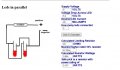
Oaky I have 11 LEDS.
I have 9V supply
I have 1V Drop Across a Transistor

I have 11 LEDS
All LEDS have a fV of 3.2V
I want all LEDS run around 20mA
To make a letter

I want one current resistor for the 10 LEDS
I want one current resistor for the 1 LED

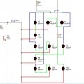
I have 5 STRINGS OF 2 LEDS in para to make the 10.

8-3.2/0.02/240/10 = 24 OHMS (27)

Will one 27OHM resistor be enough for 10 LEDS?

8-3.2/0.02 = 240 OHMS SINGLE LED

SEE ATTCHED IMAGE
 

Attachments

mcgyvr

Joined Oct 15, 2009
5,394
Nope... LEDs in parallel without their own current limiting is a NO-NO as they do not share current nicely and will eventually die..
Since your LEDs have a Vf of 3.2 you can do 5 strings of 2 on each string with a resistor for each string.
Then the single LED with its own resistor too.

150 ohm 1/4W resistor for each series string.
330 ohm 1/4W for the single LED
 

Thread Starter

englewood

Joined Jul 24, 2015
25
So then

8v - 3.2 / 0.02 = 240 / 2 = 120 (Closet highest resistor = 150) One for each string of 2 LEDS.

Why 330 ohm for the single? :-S

8v - 3.2 / 0.02 = 240 (Closet Highest Res = 270)
 

KJ6EAD

Joined Apr 30, 2011
1,581
For the calculation of the limiting resistor, you keep showing 8V - 3.2V but series strings of 2 would be 8V - ( 2 * 3.2V ) = 8V - 6.4V = 1.6V.

1.6V / 0.02A = 80Ω. The preferred value would be 82Ω.

For the single LED, ( 8V - 3.2V ) / 0.02A = 240Ω.

Your total current is going to be 120mA which is not going to be sustainable for long with a standard 9V battery. The brightness of the LEDs will drop continually over a period of approximately 4 hours.
 
Last edited:

Thread Starter

englewood

Joined Jul 24, 2015
25
So whos right ha. Im confused now.

That does make sense:

8 - 6.4 (2x3.2 VD) / 0.02 = 82

8 - 3.2 / 0.02 = 240

Its running from a 9V supply :).
 

KJ6EAD

Joined Apr 30, 2011
1,581
I'm right, of course. ;)

The BU806 data sheets I've seen don't show Vce for Ic less than 500mA so your 8V figure may be a little bit off, but if you supply the circuit with a single battery, the voltage drop at the source will be the most noticeable factor. If your supply is sustainable without drop (not a battery), no problem.
 

KJ6EAD

Joined Apr 30, 2011
1,581
So your transistor voltage drop will be 0.8V now. It probably won't make much difference but you should run the numbers to be sure.
 

KJ6EAD

Joined Apr 30, 2011
1,581
How can I make a 4017, skip Q2 -Q8?
Now you're hijacking your own thread with this off-topic post. o_O You can't "skip" any of the states on the counter but you can decode the output or shorten the sequence by resetting before it completes all ten counts.
 

Thread Starter

englewood

Joined Jul 24, 2015
25
Hold on,

Why does the calc say this for 5 x 2 LEDS?

Oh sorry, I want to do this should I make a new thread?

8 - 6.4 / 0.02 = 80 / 2 cause there 2 LEDS = 40 OHMS Makes Sense.
 

Attachments

djsfantasi

Joined Apr 11, 2010
9,237
Where do you get the 6.4 voltage drop? Parallel circuits have the same voltage across each leg. If the LED Vf is 3.2 V, the voltage drop across the two legs is also 3.2V.
 

Thread Starter

englewood

Joined Jul 24, 2015
25
Each LED has a 3.2 VD, 2 x 3.2 = 6.4.

8-6.4VD / 0.04mA = 40 ( Next res 47 OHM)

2 LEDS WITH 3.2 VD
2 LEDS WITH 0.02mA

This is want the end result is.

14.63mA through 270 OHM Res
14.55mA through 47 OHM Res cant get any closer than the :).


The calculations are correct, I have checked the current flow in Proteus through each resistor and its almost the same :)

Try this

http://www.quickar.com/bestledcalc.php?session=
 
Last edited:

djsfantasi

Joined Apr 11, 2010
9,237
You add the voltage drops in a SERIES circuit. Your LEDs are in a PARALLEL circuit where the voltage is the same in each leg. In your case 3.2V.

The calculations are correct; you are using the wrong equation.

To add to the confusion, LEDs in a parallel circuit need a resistor in each leg...
 

Thread Starter

englewood

Joined Jul 24, 2015
25
Oh idiot,

They are in Series in 2 LEDS in my Schematic. Doh!!!!!!

But why does the software show the correct mA flowing through each resistor?
 

Attachments

Last edited:
Top