Well...I thought there should be two pulses per beat...the first a normal LED intensity, the second a lower LED intensity, sort of an "intake" and "exhaust" pump per beat effect.
So the diode are general switching and the 4017 requires a clock pulse. Will an adjustment to the speed of the clock pulse say from a 555 design easily change heart beat?
Looking for a design schematic to light 4-6 LEDs in parallel. I want to install it in a plastic heart, located inside a skeleton’s chest, part of a Halloween display. I’d like it to do a (beat-beat, short time off then (beat-beat). Repeat. If possible a way to adjust the speed.
operate at 9vdc
Thanks
I need a viable circuit. Have breadboarded what has been suggested but nothing works. Simple flashing but no gap between beat beat? I want beat xx beat xxxxx beat xx beat repeat
I need a viable circuit. Have breadboarded what has been suggested but nothing works. Simple flashing but no gap between beat beat? I want beat xx beat xxxxx beat xx beat repeat
I need a viable circuit. Have breadboarded what has been suggested but nothing works. Simple flashing but no gap between beat beat? I want beat xx beat xxxxx beat xx beat repeat
Try the circuit I just posted #21. VR1 varies the speed between 50BPM and 100BPM.
The LEDs should flash to mimic the double pumping of a heartbeat. If the gap isn't wide enough, we can adjust.
I need a viable circuit. Have breadboarded what has been suggested but nothing works. Simple flashing but no gap between beat beat? I want beat xx beat xxxxx beat xx beat repeat
If we had a nickel for every time we heard that...
The solution is always the same - divide and conquer.
First make sure the timer is running. Use an LED to test. The timer should be running slowly enough that you should be able to see it flicker. If you have a multimeter, check voltage at the power pins.
Likewise check that the counter counts. You can manually apply a "clock" signal to see if the count advances. Again, you can use LEDs to to test the output. You'll usually see it skip ahead on a manual clock because it bounces but that's OK.
You can also check the output section (the transistor) by bypassing the counter and applying a manual signal.
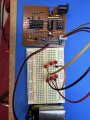
Yeah everything is working. I have a premade 555 clock bench module that’s adjustable with output power and clock signal connections. It also has a switch to an onboard LED to check operation and speed then switch to output connections to use in test circuits. It’s working fine. 4017 is also working fine as part of 10 led chaser. I moved it to another breadboard to build any ideas to try.
A few years ago I built an audio heartbeat simulator to help a new puppy sleep at night. Here is that circuit re-worked for your application. It looks like a lot of parts, but it actually has fewer components and connections than previous circuits.
U1A-R1-C1 form the basic oscillator. D1 and R4 shorten the positive half-cycle for the closely-spaced double flash. R2-C2 and R3-C3 are differentiators; these set the on time for the LEDs. If you want the second flash to be slightly less bright to more accurately simulate the diminished second thump in a heartbeat, reduce R3. The shorter flash sill be seen as dimmer.
The heart of the circuit is U1C. This acts as an inverted-input OR gate, the DeMorgan equivalent of a standard NAND gate. If either input goes low, the output goes high and turns on the LEDs through Q1.
I prototyped this circuit, and these values give a decent approximation of a heartbeat. None of the part values are critical, and can be scaled to work with parts you already have. For example, increasing R2 and R3 to 1.0M and decreasing C2 and C3 to 0.047 uF will give the same results. Decreasing R2 and R3 to 330K and increasing C2 and C3 to 0.15 uF will have similar results.
C4 is the power supply decoupling capacitor for U1. It should be located as close as possible to the IC power and GND pins.
Overall, the circuit has four R-C timers. Two of them form the squarewave oscillator with a non-50/50 duty cycle, and two form the two flashes. All four can be made adjustable by replacing the fixed resistor with a smaller fixed resistor in series with a trimpot. For example, R1 has the major effect on the circuit's heart rate. Decreasing R1 to 750K and adding a 500K pot in series gives a reasonable adjustment range. This adjustment will affect both the overall frequency and the time delay between the two flashes. To make that time delay independent of the frequency, add a diode in series with R1 as in eetech's schematic #20.
Is it just me, or is there no reason for R2, D2, or U1B? Other than basic frequency, the clock signal duty cycle and phase have no effect on the output pulses of a 4017. The output pulse widths are set by the input frequency only; narrow or wide clock pulses do not appear at the outputs. The oscillator period sets the on-time of a single flash, and the number of outputs skipped over sets the time delay between flashes. U1 and all of its components can be replaced with a 555, 1 R, 1 C, and 1 pot.
U1B initially clocks U2 on positive edge, without U1B, U2 would clock at power on.
Its been a while, so I don't remember if that matters, other than changing the initial delay.
Other than basic frequency, the clock signal duty cycle and phase have no effect on the output pulses of a 4017.
It seems what I've shown, in effect, is really only changing frequency.
I tested this on bench with a pulse generator. I'd have to test with CD4093B.
The output pulse widths are set by the input frequency only; narrow or wide clock pulses do not appear at the outputs. The oscillator period sets the on-time of a single flash, and the number of outputs skipped over sets the time delay between flashes. U1 and all of its components can be replaced with a 555, 1 R, 1 C, and 1 pot.
A few years ago I built an audio heartbeat simulator to help a new puppy sleep at night. Here is that circuit re-worked for your application. It looks like a lot of parts, but it actually has fewer components and connections than previous circuits.
U1A-R1-C1 form the basic oscillator. D1 and R4 shorten the positive half-cycle for the closely-spaced double flash. R2-C2 and R3-C3 are differentiators; these set the on time for the LEDs. If you want the second flash to be slightly less bright to more accurately simulate the diminished second thump in a heartbeat, reduce R3. The shorter flash sill be seen as dimmer.
The heart of the circuit is U1C. This acts as an inverted-input OR gate, the DeMorgan equivalent of a standard NAND gate. If either input goes low, the output goes high and turns on the LEDs through Q1.
I prototyped this circuit, and these values give a decent approximation of a heartbeat. None of the part values are critical, and can be scaled to work with parts you already have. For example, increasing R2 and R3 to 1.0M and decreasing C2 and C3 to 0.047 uF will give the same results. Decreasing R2 and R3 to 330K and increasing C2 and C3 to 0.15 uF will have similar results.
C4 is the power supply decoupling capacitor for U1. It should be located as close as possible to the IC power and GND pins.
Overall, the circuit has four R-C timers. Two of them form the squarewave oscillator with a non-50/50 duty cycle, and two form the two flashes. All four can be made adjustable by replacing the fixed resistor with a smaller fixed resistor in series with a trimpot. For example, R1 has the major effect on the circuit's heart rate. Decreasing R1 to 750K and adding a 500K pot in series gives a reasonable adjustment range. This adjustment will affect both the overall frequency and the time delay between the two flashes. To make that time delay independent of the frequency, add a diode in series with R1 as in eetech's schematic #20.
U1B initially clocks U2 on positive edge, without U1B, U2 would clock at power on.
Its been a while, so I don't remember if that matters, other than changing the initial delay.
It seems what I've shown, in effect, is really only changing frequency.
I tested this on bench with a pulse generator. I'd have to test with CD4093B.
 Facebook
 Google
 GitHub
 Linkedin