I am making an amplifier for a piezoelectrical sensor to collect heartbeat data

Thread Starter

almaz_so

Joined Jul 3, 2023
10
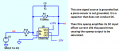
Hello. I am designing an amplifier which amplifies the signal of a heartbeat( around 1Hz) that is collected from a piezoelectric sensor. I aim to have a ~1V amplitude sine wave output at 1 Hz, and the waveform of other frequency will be filtered out. But right now, I only have an output of 0.16V amplitude sine wave.

Is there any way to increase the gain of the circuit and have a higher voltage output?


1.png
Figure 1 Circuit Diagram

3.png
Figure 2 Circuit Diagram (with notes)

2.png
Figure 3 Output Waveform
 

Thread Starter

almaz_so

Joined Jul 3, 2023
10

Attachments

Thread Starter

almaz_so

Joined Jul 3, 2023
10

ericgibbs

Joined Jan 29, 2010
21,390
hi almaz,
Cleaned up your original asc circuit, it should make it easier to follow any changes you have to make in order to get it working as required.
Correct the excessive gain in the 1st stage.

Don't worry about using boxes for the symbols.
E
EG57_ 941.png
 

Attachments

Ian0

Joined Aug 7, 2020
13,097
The charge amplifier in the simulation has a DC gain of zillions that amplifies the opamp DC input offset voltage.
Agreed. What’s this obsession with charge amplifiers for piezo transducers. What’s wrong with an ordinary non-inverting op-amp stage, using a FET op-amp to get a high-impedance input?
Do the filters need to be so complicated? Has the TS quantified the interference signals that need to be removed?
 

Thread Starter

almaz_so

Joined Jul 3, 2023
10
hi almaz,
Cleaned up your original asc circuit, it should make it easier to follow any changes you have to make in order to get it working as required.
Correct the excessive gain in the 1st stage.

Don't worry about using boxes for the symbols.
E
View attachment 297647
But If I use another model (the one with the voltage source) of the sensor, the maximum gain will be around 10dB
5.png
 
Top