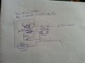
Anybody please review this circuit and give me the suggestions. I want to drive a laser diode with vf of 3 to 3.5v and works with a constant current of 300mA.
Lm317 need at least 3v higher than the output. My source is only 3.7v and vf of the led is 3~3.5v. So it would not work. Unless if there is a way to amplify the volts before lm317.
Ya I know. But the lm317 will drop some voltage. So if I use 3.7v battery when it passes through lm317 it drops 2v so I will get only 1.7v which is not sufficient for laser diode. The source should be at least 6v for it to work using lm317.
How to check tour library. And is this circuit OK? Or it need changes? If need changes I will first study your library. But how to get into your library.
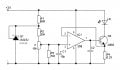
Your circuit wont work, as a TL431 has an internal reference of 2.5v, your better off supplying the led direct from the power with a transistor and diodes.
Your circuit wont work, as a TL431 has an internal reference of 2.5v, your better off supplying the led direct from the power with a transistor and diodes.
V_R4=300mA*0.33Ω=0.099V.
The V_R1 is quite low, so the current flows through the R1,R2 and Pot also will be low, and the range of (+) input voltage should be around 0.08V~0.2V or some more range.
V_R4=300mA*0.33Ω=0.099V.
The V_R1 is quite low, so the current flows through the R1,R2 and Pot also will be low, and the range of (+) input voltage should be around 0.08V~0.2V or some more range.
I did not understand.
According to what I studied with my own self reading here and there
the shunt regulator getting very low current due to R1 and that will be iR1= 3v/660 = 4.54mA. and due to R2 and pot the shunt regulator outputs voltage = Vref * (1+R2/Pot) = 2.5 * (1+10k/10k) = 5V.
The current gain of d882 is 150.
so if the current input receiving by d882 is 4.54ma. the current flow from collector to emitter is 150 times 4.54mA.
ie. 4.54*150 = 681mA. I don't know what is the use of R3 and R4. and what is the use of lm358 there? if it is just acting as switch.
how much voltage will be near - pin of lm358? how to calculate the voltage near - pin. and if positive pin is more than the negative pin. the output will be 3v right?
Let me explain what I am doing. before that. I have to thank you for teaching me and taking your time for me. May God bless you.
According to the datasheet the zener diode current is as follows:
IR1 = 3-2.2 / 120 = 0.006666A. i.e. 6mA.
Voltage near R1 = 0.00666 * 120 = 0.7992V
Voltage near R2 = 0.7992V * 200 / (2000+200) = 0.7265V (I don't know how you got 0.098V)
According to you voltage near + is 0.098V and near - is 0.099V. Since - is higher lm358 output near 1 is 0. (am I right?)
please tell me what will be the output of lm358 in that condition. and how much voltage is going to d882 transistor base?
If you like to calculate more details then the base of Q3 need a resistor Rb_Q3, and the C_Q3 is 300mA, and I_RbQ3 is 30mA, so the Ie_Q3 is 330mA.
The (-) about V- = 330mA* 0.33 ohms = 0.109V.
So the V(+) of op amp should be adjust the voltage about 0.09V~0.2V, you can over the range, but just don't small than that.
Normally the V(+) should higher than the V(-) a little, when the V(-) big than V(+) then the output of o amp will turn to low and the Q3 will be turn off.
 Facebook
 Google
 GitHub
 Linkedin