LED constant current source scheme

SgtWookie

Joined Jul 17, 2007
22,230
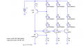
OK, look - if you know the voltage is going to be pretty stable, your best bet would be to take that 24v, subtract 1v from it, and divide the result by the typical Vf of your LEDs at their specified current.

For example:
Let's say you're planning on using a number of white LEDs that have a typical Vf of 3.5v @ 25mA
24v-1v = 23v; 23/3.5v = 6.57... Take the integer value, which is 6. That's how many 3.5v LEDs you can have in a series string.
6 * 3.5 = 21v. So, you have 3v left to drop across a resistor.
The question is now, what size resistor do you need to drop 3v when you have a current flow of 25mA?
R = E/I, or Resistance(Ohms) = Voltage / Current
R = 3v/25mA = 3/0.025 = 120 Ohms
Let's check to see how much power will be dissipated across the resistor.
P = EI, or Power(Watts) = Voltage * Current
P = 3 * 0.025 = 0.075 Watts, or 75mW. We double the wattage to make sure it'll be reliable, so 150mW. You could use 1/4W resistors. 1/8 W resistors would be pushing your luck, as they can only dissipate 125mW.

So, let's look at total power dissipation in the circuit.
75mW in the resistor
21v * 25mA = 525mW in the six LEDs in a series string.
525mW + 75mW = 600mW. 525mW/600mW = 87.5% efficient.
Parts count per string: 6 LEDs, one resistor. It doesn't get a whole lot more simple than that.

Let's look at the other scenario with the regulator.
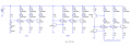
You're starting off with 3 LEDs per string, plus two resistors and a transistor. There's a fixed "overhead" for the strings of one LM317 regulator.

The regulator is really being used as a current regulator in this case - so you'll have a minimum 1.7v drop across it, plus the drop across Rsense, which in this case would be:
R = 1.25/DesiredCurrent = 1.25/0.025A = 50 Ohms
E = IR (Voltage = Current * Resistance, so 25mA * 50 Ohms = 1.25V drop
1.7v+1.25v=2.95v, hence the standard line that in current regulation mode, the LM317 drops 3v across itself.

So, the three LEDs drop 3.5 * 3 = 10.5v across themselves.
This means that the LM317 drops the remaining 24v-10.5v=13.5v across itself.
P=EI, so the LED's power consumption is 10.5v*25mA= 262.5mW
The remaining power dissipation is 13.5*25mA=337.5mW
Total power dissipation is therefore 600mW, with efficiency of 262.5mW/600mW= 43.75% efficient. :(

Relatively complex, relatively inefficient, and no guarantee of better regulation - actually, regulation will be worse unless all LEDs used have the same Vf.

You might think you could use six LEDs in a series string - but then you would not have enough "overhead" for the regulator to properly regulate.

There isn't a good point to use a current regulator in your circuit, because you already have a voltage regulator. All you need is a current limiter, calculated as I did in the first example.
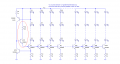
 

Thread Starter

toughspeaker

Joined Jan 28, 2009
40
Again thanks alot Sgt Wookie.

I fully understood the first scenario, no questions to ask.

In your second scenario, are we taking the PN2222 = MPS2222 also into consideration? Is that what you mean with the current regulator? Or is the PN2222 being omitted? (I ask this lame question because of wanting to avoid any misunderstandings.)

(The whole deal with the current regulator LM317 and putting up with its inefficiencies and not using just a resistance as the only current limiting component, is that one can use the PN2222 in combination with the LM317 so that if a LED in a series would magically somehow blow, PN2222 steps in and allows no current to pass through, thus saving the remaining LEDs. As mentioned, why bother with the LM317 if you can't use the PN2222 with it?)
 
Last edited:

Wendy

Joined Mar 24, 2008
23,797
If you have a resistor per chain then the other LEDs won't blow. The worst that will happen is the other LEDs in the chain will go dark (but are good, and will resume working after repairs are made). As long as good design practices are used LEDs are very robust. I have seen designs that used LEDs in parallel without separate resistors, it's not something I would do. That self adjusting current regulator was a neat gimmick, but it wasn't really that practical. Speaking for myself I would rather use each transistor in a leg as a current regulator, but for anything resembling a stable power supply that is also overkill and unnecessary.
 

Thread Starter

toughspeaker

Joined Jan 28, 2009
40
If you have a resistor per chain then the other LEDs won't blow. The worst that will happen is the other LEDs in the chain will go dark (but are good, and will resume working after repairs are made)
I don't quite understand how you mean the setup would look like with one resistor per chain. For the sake of clarity, the setup is now the following omitting the pn2222:

24V powersupply, 1 LM317, then comes the Resistor on its adj pin, the "post-resistor-adj-pin" reunites with the out-pin of the LM317 and now comes a chain of LEDs. With this setup, if a LED were to blow, all the other LEDs were to shine brighter and eventually die. How could one have a resistor per chain? I'm sorry for being such an amateur.

The PN2222 is a neat gimmick
Why is the PN2222 just a neat gimmick? What is the rationale behind it? If the PN2222 could regulate the powersupply and at the same time being efficient (meaning that the transistor itself and that the extra Resistors
dont use up too much current) then I would definately go for the setup with the PN2222 included, since the PN2222 doesn't cost much.

Bill, perhaps it's too much asked but do you mind doing the calculation for me with the 24 V powersupply, LM317, the PN2222 and a chain of 3,5V 25 mA LEDs? What values would the resistors R4 and R1sense have? Is that what our Sergeant did a couple of posts ago? If so then forget this question, but I think he omitted the PN2222 when doing the maths.
 
Last edited:

Wendy

Joined Mar 24, 2008
23,797
You are getting very mixed up here. I was not talking about the transistors. Reread what I said. If you have a resistor per chain (as the article I wrote suggested) then none of this is an issue. It is simple, it works reliably, and you're not going to blow any other LEDs if one LED goes out.


You don't want to share a single current regulator among all the chains, which is what I said 2 posts ago. If you are going to have a transistor per chain anyhow, use the transistor as a current regulator (they do a good job for this). You will note each chain still has a separate resistor per chain.


However, if the power supply is stable, none of this is needed, refer back to the first illustration, a resistor per leg.

Again, to clarify, this circuit is a gimmick...


There is no real benefit to it, it absorbs too much voltage, and while it works, it is overcomplicated. There are simpler ways that plain work better. The LM317 is a good chip, but it needs to work for us, it is not an absolute necessity in any design.

Didn't I read that your power supply is regulated? Then adding a second regulator is redundent and counter productive.
 
Last edited:

Thread Starter

toughspeaker

Joined Jan 28, 2009
40
Thanks for clearing things up Bill! I now fully understand.

Sorry for pressing the issue but i just really really really have to know this: Let's assume I didn't have a regulated 12 V powersupply. In such a case, the usage of the LM317 and the PN2222 would be logical. What would the R4 and RSense1 become for one chain of 3,5V LEDs?
 

SgtWookie

Joined Jul 17, 2007
22,230
Sorry for pressing the issue but i just really really really have to know this: Let's assume I didn't have a regulated 12 V powersupply. In such a case, the usage of the LM317 and the PN2222 would be logical. What would the R4 and RSense1 become for one chain of 3,5V LEDs?
Rsense = 1.25/DesiredLEDCurrent.
So, if you wanted 20mA current through your LED string:
Rsense = 1.25/20mA= 1.25/0.02 = 62.5 Ohms.
1k would work for R4.

Since the LM317 is being used in current regulator mode, there's that pesky 3v minimum dropout voltage to deal with; so keep that in mind.

Your example LEDs have a Vf of 5v. So, to light just one LED in a string, you'll need a minimum of 8v; for two you'll need 13v; for three, 18v.
 

Ron H

Joined Apr 14, 2005
7,063
You can make the current more nearly independent of Vcc with some simple improvements. Below are some ideas, with a comparison of output current vs Vcc. The "corner" voltage is dependent on the number of LEDs in the string, and the voltage drop of each LED. The circuit with the PNP may not be practical if the LEDs are located remotely from the current sink, as oscillations may occur. A 100nF cap from the base of the current sink to GND may be helpful, and should also stabilize the circuit in the middle, if oscillations occur (not likely).
I have included the .ASC file for LTspice simulation.
 

Attachments

Thread Starter

toughspeaker

Joined Jan 28, 2009
40
I cannot stress how thankful I am for the tips and tricks you guys are giving me. Very very friendly of you.

Ron, do you know how efficient your setup is? How much current goes towards heat and how much will actually make the LEDs do real work?

And your QTLP SMD LEDs are rated Vf 2,5V 30ma, how do one have to change resistances so that one can run "normal" blue 3,5V 20ma LEDs with it?
 

Ron H

Joined Apr 14, 2005
7,063
I cannot stress how thankful I am for the tips and tricks you guys are giving me. Very very friendly of you.

Ron, do you know how efficient your setup is? How much current goes towards heat and how much will actually make the LEDs do real work?
In all 3 circuits, the current sink dropout voltage is about 1V. This means that if the collector of a sink transistor drops below 1V, the current will be a huge function of Vcc. If, for example, your total LED drop is 10.5V (3*3.5V), you would need a minimum of 11.5V Vcc to maintain constant current. If Vcc is higher, you are wasting power. A series regulator will not help, as it also wastes power. This is true of any linear (non-switching) current source.

"Wasted" current flows through the transistor bases and through the reference transistor (or diodes) and the bias circuitry for these. In the circuit below, assuming a minimum beta of 100 and 20mA in each leg, the total base current would be (60mA/100) 600uA. The PNP current source would need to supply this current, plus some current for the reference transistor. I would make Iref at least 3 to 5 times the maximum base current, so that the reference voltage (Vbe of Q4) is not excessively dependent on beta. So, if you make the Q5 bias current 3mA, that current is wasted in the sense that it does not pass through the LEDs.


And your QTLP SMD LEDs are rated Vf 2,5V 30ma, how do one have to change resistances so that one can run "normal" blue 3,5V 20ma LEDs with it?
I just used those LEDs because I had a model for them. You can use any low-current LED (0-50mA or more) so long as you design the current sources to supply the current, and keep power dissipation in mind.
The currents are equal to Vbe of Q4 (≈0.7V) divided by the emitter resistances R1, R3, and R4.
 

Attachments

GioD

Joined Mar 20, 2009
30
I very appreciate the circuit and I want to try it. Only a question.
How many transistor bases is possible to parallel connect ?


In all 3 circuits, the current sink dropout voltage is about 1V. This means that if the collector of a sink transistor drops below 1V, the current will be a huge function of Vcc. If, for example, your total LED drop is 10.5V (3*3.5V), you would need a minimum of 11.5V Vcc to maintain constant current. If Vcc is higher, you are wasting power. A series regulator will not help, as it also wastes power. This is true of any linear (non-switching) current source.

"Wasted" current flows through the transistor bases and through the reference transistor (or diodes) and the bias circuitry for these. In the circuit below, assuming a minimum beta of 100 and 20mA in each leg, the total base current would be (60mA/100) 600uA. The PNP current source would need to supply this current, plus some current for the reference transistor. I would make Iref at least 3 to 5 times the maximum base current, so that the reference voltage (Vbe of Q4) is not excessively dependent on beta. So, if you make the Q5 bias current 3mA, that current is wasted in the sense that it does not pass through the LEDs.


I just used those LEDs because I had a model for them. You can use any low-current LED (0-50mA or more) so long as you design the current sources to supply the current, and keep power dissipation in mind.
The currents are equal to Vbe of Q4 (≈0.7V) divided by the emitter resistances R1, R3, and R4.
 

Ron H

Joined Apr 14, 2005
7,063
I very appreciate the circuit and I want to try it. Only a question.
How many transistor bases is possible to parallel connect ?
With the previous circuit, I would probably not go over 10 parallel current sinks.
If you add a transistor and a resistor, I think you can go to 100 or more. It works well in simulation. I didn't test it in hardware. It might oscillate.
In either circuit, keep in mind that you do not have to have the same number of LEDs in each string.
 

Attachments

GioD

Joined Mar 20, 2009
30
Thanks Ron H, thanks to all.
I’m going to draw a professional circuit with 100 White leds. In my circuit, I have 18 strings of leds, some with 5 and some with 6 leds. The power supply is 24Vdc. I think that is an important thing to control the current of the leds, for several reasons. Monday I make a prototype and test the circuit with 4 or 5 string.
How do you think about circuit reliability and behaviour to electrostatic discharge, burst and surge ?
I have some CE instruments, I want to make some tests.
I don’t see any capacitor in the circuit, do you think that is better to introduce one between the bases and the gnd ? Or it can worst the behaviour because it slow the current limitation ?
I think that a pretty thing is to introduce a soft start, so is similar to halogen lamp. But it can have a bad behaviour if the power supply have ripple. Anyone have an idea ?
 

Ron H

Joined Apr 14, 2005
7,063
I just realized that the circuit may not start if you don't add a 100k resistor from the base of Q103 to ground. I'll think about the soft start.
 

Wendy

Joined Mar 24, 2008
23,797
A large capacitor across the diodes on my version would soft start. Other than the special effect there is no advantage to it, but then, special effects are legit.

The capacitor won't care about ripple, if anything it will reduce it. Increase the gain of the regulator transistor with either a Sziklai pair a Darlington pair. I like Sziklai pairs because they only drop the standard 0.7V on the BE junction.

The thing I don't like about this design is it uses one LED as a reference, which is OK, but what happens if something goes off with that one chain? It doesn't help my cause that I don't really understand the feedback on it too well, I'm still working on its theory of operation.


This design, one I tend to advocate, is just a basic voltage regulator followed by simple current regulator. I'd use the Sziklai pair for the voltage regulator, which would allow the Base to ground resistance to increase dramatically and allow the design to boost the current providing resistor to a much larger value to increase the RC time constant. I've modified the base design to add the soft start.

 
Last edited:

GioD

Joined Mar 20, 2009
30
Hi Bill,
I'm agree with you when you write that the reliability of the circuit is connected to a LED. What do you think about the use of a voltage reference ic to drive all the transistor bases ?
 
Last edited:

Wendy

Joined Mar 24, 2008
23,797
That would work too. The goal is to keep the voltage as low as practical across the emitter resistors, which allows the current regulator to drop as little voltage as possible.
 

Ron H

Joined Apr 14, 2005
7,063
Bill, I think your soft start would be better if you put the cap across the grounded diode only. The reference voltage has to reach two diode drops before current begins to flow. Bypassing only one diode avoids most of the delay that would otherwise occur before current begins to flow in the LEDs.
 
Top