LED constant current source scheme

Wendy

Joined Mar 24, 2008
23,429
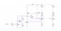
I thought about that, not quite from the angle you're talking about. My thought was a switch across CR2 and CR3 to turn the circuit on or off. I like your idea better, putting C1 across CR3.

You can also turn it on and off with a simple transistor across the diodes. I'll draw it in too, but it can be eliminated.


GioD

Joined Mar 20, 2009
30
Hi to all,
I think that the above circuit can be good and not led dependent, so more reliability. Also a great idea, the control transistor. Do you think that it can drive 18 transistor bases ? And how can I calculate Rz ?
 

Wendy

Joined Mar 24, 2008
23,429
I'd play with it on a breadboad. With the transistor driver the limitations are expanded, 18 legs are no problem.

The mix of Rz and C1 determine the start up time. I figure you can go up to 100KΩ with no problems, but that would be a top limit. Figure 10KΩ and 100µF would be around 1 second.
 

GioD

Joined Mar 20, 2009
30
I'd play with breadboard, too. But the soft start don't work, it start immediately at maximum current. Then, the current is regulated, but it vary if I connect or disconnect Q2. I check the circuit, and it seem right. I use BC237 NPN and BC327 PNP, can it be a transistor type problem ?
 

Attachments

Wendy

Joined Mar 24, 2008
23,429
It is probably the range isn't that that wide. A capacitor charges to .7 (70%) of the power supply voltage in 1 time constant (RC), and we are going for .7Volts out of what, 24V? Try upping the resistor to 100KΩ, or even 1MΩ, to see what happens.

The discharge for C1 is nonexistant, not sure how to handle that one, if it needs handled at all.
 

GioD

Joined Mar 20, 2009
30
Hi Bill,
what type of transistor do you use ? And what do you think about the variation of current attaching more transistor bases ?
 

Wendy

Joined Mar 24, 2008
23,429
It depends a little on the gain of the transistors, but not as much as you would think. I usually use a gain of 50 for worst case, so 2X 50 is a gain of 2,500 for the Sziklai pair, worst case.

As long as they can handle the current (which isn't much) I really don't think the type of transistor matters much. I tend to use 2N2222A and 2N2907A, because they are common in my neck of the woods.

Here is the logic I used, figure 36Ω X 3 transistors gain (50X50X50), the loading of each leg is around 4.5MΩ. I'm oversimplifing, but the base logic is OK. Most transistors have even more gain, so it gets better.

Each individual leg loads the total by 36Ω X 50, or 1,800Ω.
 

Ron H

Joined Apr 14, 2005
7,063
One consideration with going to 100k is that the Vfwd of the diodes is low. To compensate for this, the emitter resistor values have to be reduced to get the current up.
A potential problem is that the diode tempco is now a considerably larger percentage of the total forward voltage, making the LED current vary more with temperature.
Bill, if you don't have a simulator, you should.:) They can show you things that you might not have thought about.
 

GioD

Joined Mar 20, 2009
30
Ron,
I appreciate your simulation method. But, the circuit is now dependent by the first leds leg. What’s happen if there is a damage in the first leg and it open ? Is possible to completely separate the led electronics to the common drive and soft start circuit ?
 

Ron H

Joined Apr 14, 2005
7,063
Ron,
I appreciate your simulation method. But, the circuit is now dependent by the first leds leg. What’s happen if there is a damage in the first leg and it open ? Is possible to completely separate the led electronics to the common drive and soft start circuit ?
In simulation, if one of the LEDs in the first leg fails open, the current in the remaining legs stays almost the same.
The power dissipation of the PNP could be a little high if any LED fails open, but Bill's circuit has the same problem, possibly to a lesser extent. It can be solved a couple of different ways. You can add a resistor in series with either the collector or the emitter of the PNP (≈500Ω). It should probably be a 0.5W resistor.
 
Last edited:

Ron H

Joined Apr 14, 2005
7,063
If you just take Bill's circuit and replace the 3 reference diodes with 3 diode-connected transistors (base shorted to collector as anode, emitter as cathode), you will get better thermal stability. If thermal stability doesn't concern you - never mind.
 

GioD

Joined Mar 20, 2009
30
Hi ron,
I make your circuit on the breadboard. It’s very strange but it has a double oscillation. Measuring the voltage across R1 (I used 33ohm), there is a 132ms time when the voltage is about stable at 528mV and a 192ms time when the voltage have a 63Khz oscillation with a 840mV peak. I check the circuit and it seams right done.

The Bill’ circuit work good, but I see the thermal instability. Regarding the soft start of Bill’ circuit I have to increase the RC time (47K 470uF) and put a resistor to discharge the capacitor.
 

Wendy

Joined Mar 24, 2008
23,429
I may be mistaken (I frequently am) but I think you only need 2 BE junctions, the 3rd diode sets the voltage across the current programming resistors.
 

Ron H

Joined Apr 14, 2005
7,063
I may be mistaken (I frequently am) but I think you only need 2 BE junctions, the 3rd diode sets the voltage across the current programming resistors.
You're right. One of the PN junctions can still be a diode (it can also be a BE junction). In simulation, that lowered the voltage across the current programming resistors by about 100mV. Thermal stability was a little worse. When the temperature changed from 25C to 50C, the current change using the 2N3904 reference was about 6.7%. With the 1N4148 reference, the change was about 9.5%. I don't have models for BC237 ar BC327.
 

Ron H

Joined Apr 14, 2005
7,063
Hi ron,
I make your circuit on the breadboard. It’s very strange but it has a double oscillation. Measuring the voltage across R1 (I used 33ohm), there is a 132ms time when the voltage is about stable at 528mV and a 192ms time when the voltage have a 63Khz oscillation with a 840mV peak. I check the circuit and it seams right done.

The Bill’ circuit work good, but I see the thermal instability. Regarding the soft start of Bill’ circuit I have to increase the RC time (47K 470uF) and put a resistor to discharge the capacitor.
I see oscillation on the sim after changing the transistor types. I also saw it with the 2N3904/06 combo, but not until you pointed it out. I had to change the minimum step size on the simulator to bring it out. Oscillations in Spice simulators are sometime hard to get started. Even after I saw them, they were nothing like what you described.
I wasn't surprised that oscillations occurred, because the circuit is a feedback loop, and feedback loops are prone to oscillate. Worse yet, the Sziklai pair is a feedback loop within the main loop.
You might get rid of the oscillations by adding a 1k resistor across the PNP base-emitter, and another 1k from the collector to GND.
Having said all that, you can get near-perfect temperature stability if you use an op amp. See below. This idea is nothing new, but I don't know if you had seen it.
I took the LED driver out of the loop, at the expense of 20+mA of extra current, which I doubt will be a problem for you.
 

Attachments

GioD

Joined Mar 20, 2009
30
I have add the two resistor. The circuit is more stable, but sometimes have strage behaviour and an oscillation at Mhz frequency. Tomorrow I try the circuit with the Opamp. :cool:

I see oscillation on the sim after changing the transistor types. I also saw it with the 2N3904/06 combo, but not until you pointed it out. I had to change the minimum step size on the simulator to bring it out. Oscillations in Spice simulators are sometime hard to get started. Even after I saw them, they were nothing like what you described.
I wasn't surprised that oscillations occurred, because the circuit is a feedback loop, and feedback loops are prone to oscillate. Worse yet, the Sziklai pair is a feedback loop within the main loop.
You might get rid of the oscillations by adding a 1k resistor across the PNP base-emitter, and another 1k from the collector to GND.
Having said all that, you can get near-perfect temperature stability if you use an op amp. See below. This idea is nothing new, but I don't know if you had seen it.
I took the LED driver out of the loop, at the expense of 20+mA of extra current, which I doubt will be a problem for you.
 

Ron H

Joined Apr 14, 2005
7,063
I have add the two resistor. The circuit is more stable, but sometimes have strage behaviour and an oscillation at Mhz frequency. Tomorrow I try the circuit with the Opamp. :cool:
Make sure you use the right op amp. Not all op amps will work in this circuit. The input common mode range needs to include the negative rail (ground), the output has to be able to go very near ground, and the op amp has to work on 24V. The last two requirements can be overcome with some circuit tricks, but the input common mode range is difficult to overcome.
You can use an LM324, which is common and is the quad version of the LM321, but you can't let the other 3 sections float. If you want to use LM324, tie one input of each unused section to ground.
 

Wendy

Joined Mar 24, 2008
23,429
The modern LM324 is very inexpensive, available everywhere (including Radio Shack), and has some impressive power supply specs. It is also slow, and for op amp technology, pretty old. I would definately put it on my list of parts for a breadboard kit.
 

Audioguru

Joined Dec 20, 2007
11,248
I use the MC33174 to replace the lousy old LM324, the MC33172 to replace the lousy old LM358 and the MC33171 to replace the lousy old LM321.
They have exactly the same low power supply current, the same input that works down to the negative power supply voltage (ground if a single supply), the same output that can go to ground if a single supply and the same 3V minimum allowed supply voltage.

But these Motorola/ON Semi opamps do not have the horrible 3% crossover distortion (it is only 0.03%) and have a full output bandwidth that is 35 times more (to 35kHz) than the lousy old ones. Their max allowed power supply voltage is 44V which is 12V higher than the lousy old ones.
 
Top