 Facebook
 Google
 GitHub
 Linkedin
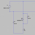
Why there are 2 diodes present around LED. Can anyone tell me why it is done so. Will it remain on in normal condition or remain off.
I want to use led whose dataheet is attached. Which one on ltspice would be best suited.
I want to use led whose dataheet is attached. Which one on ltspice would be best suited.
Attachments
-
 34.1 KB Views: 33
 -
961.3 KB Views: 7


