LDO on new circuit design is dropping out

Thread Starter

dcbingaman

Joined Jun 30, 2021
1,065
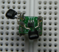
I've never seen this type of Prototyping done before,
but then again, I only dabble around the edges of Digital Stuff.

My estimation is that this type of layout is a complete and utter disaster,
but what do I know, it might be common practice.

Some things just can't be expected to perform correctly when
implemented in this "patchwork" fashion.
I estimate that You may never get this project to operate reliably in this form.
I think You will be chasing your tail trying to diagnose "the next" problem.
This is one of the reasons that I don't think much of SMD Devices when it comes
to "Maker-Projects" or DIY / Hobbyist type projects that will never be
put into Commercial-Automated-Mass-Production.

This Project would be easier to implement on a Large Perf-Board,
with mostly Through-Hole-Parts.

Figure on designing 2 or 3 or more proper, professionally manufactured,
Multi-Layered, SMD Circuit-Boards,
before You end up with a reliable product.

But remember,
I may have no-clue of what I'm talking about,
this is just my take on it,
and more experienced People should be consulted.
There are plenty here, and I'm sure they will chime-in.
.
.
.
Attached is the gerber files for the final PCB board if you want to take a look.
 

Attachments

Thread Starter

dcbingaman

Joined Jun 30, 2021
1,065
Can you add a small leaded ceramic capacitor directly form the LDO input pin to the LDO ground pin on the breadboard?
Good idea. I tried that with a 0.1uF and a 1uF ceramic caps. It did not make any difference. I kept it as close to the pins on the breakout board as I could (right next to them). But worth a shot. Thanks.
 

Thread Starter

dcbingaman

Joined Jun 30, 2021
1,065
The datasheet says what value and what type of input and output capacitor to use.
Correct. It recommends 0.47uF ceramic cap or higher. I have placed a 1uF ceramic cap on the output. Both the input and output have 10uF ceramic caps on them per the datasheet which specifies a value of 0.47uF ceramic cap or higher. On the schematic you will see 10uF caps on LDO input and output. Both are ceramic caps per the LDO datasheet. Also, all IC's in the circuit have 0.1uF ceramic caps from Vcc to Ground per manufacturers recommendations.
 
Last edited:

Thread Starter

dcbingaman

Joined Jun 30, 2021
1,065
The rows of contacts and wires on the breadboard are series inductors that cause the capacitors not to do their function.
Good idea. To test that theory I modified the adapter board and soldered the input and output capacitors with value of 1uF ceramic directly to the pins keeping the cap leads as short as possible (see attached). Retested the circuit with that modification but it did not fix the issue.

1630342937139.png
 

Thread Starter

dcbingaman

Joined Jun 30, 2021
1,065
I replaced the LDO with another one. This one the circuit works but when you look at the 3.3V power on the scope it is still dropping down to 2.4V as compared to 2.0V. So this LDO is doing a little better than the other as far as minimum voltage to the microcontroller is concerned. I have attached the picture of dropout. I have a theory the wireless UART transmitter is somehow interfering with the regulator. Another change: I grounded all unused IO on the microcontroller. Note the dropout time is about 16ms this is approximately the time for the wireless UART to send data out. Note: The PIC transmits the data to the wireless UART before this event.

1630345042825.png
 

Thread Starter

dcbingaman

Joined Jun 30, 2021
1,065
Good news! I finally figured out what is going on! There was more than one grounding path from the regulator to the microcontroller when I removed this path and provided a direct path from the regulator ground to the microcontroller the problem is fixed!
Thanks to everyone who helped me with ideas on troubleshooting. I am certain this will not be an issue with the PCB.
 

graybeard

Joined Apr 10, 2012
118
When interpreting the Data-Sheet for a Regulator,
Transient-Response-Graphs will usually be provided.

There are 3 general types of Bypass-Capacitors, each having their own characteristics.
Electrolytic,
Tantalum,
and Ceramic.
If You see the Output-Capacitance being specified at ~2.2uf, that's usually
referring to a Tantalum-Capacitor,
which is "fast enough" for most low-Frequency Applications.

If it specifies anything larger than that, it's usually referring to an Electrolytic-Capacitor,
often referred to as a "Bulk-Storage-Capacitor".
These are somewhat "slow" and can't keep-up with high-Frequency-demands,
so,
they are usually specified along with a Ceramic-Capacitor,
which type is much more capable of handling high-Frequency-demands.

If the Data-Sheet specifies an Output-Capacitor that is less than ~2.2uf,
they are normally referring to a Ceramic-Capacitor only.

Keep in mind that Capacitors of any type have specifications that will
determine their suitability and performance in a given situation.
Sometimes a variety of different types are used in parallel for maximum performance.

You MUST HAVE Ceramic-Bypass-Capacitors,
preferably situated as close to the Power-Input-Pins as is possible.
Bulk-Capacitors "may be" optional,
that is, if the regulators can easily supply the "worst-case" maximum-Current.
.
.
.
Great rule of thumb. Can you add when one might want to use other types of caps such as mylar?
 

LowQCab

Joined Nov 6, 2012
5,101
I'm not an expert on Capacitors.
I wouldn't use a Mylar-Capacitor for Power-Supply bypassing
simply because I've never seen them used in that role,
and there's probably a good reason.
 

dendad

Joined Feb 20, 2016
4,641
Good bypassing is very important.
I generally use both a 100nF ceramic and a 10uF Tantalum cap on the input and output of the regulators, as close to the chip as I can. And that seems to work very well.
Also, there will be quite a few extra 100nF caps around the circuit, generally on for each IC, and an occasional extra 10uF Tantalum.
Lots of my boards have been running for many years without problems in industrial control and building management roles.
Although the one trouble is after about maybe 10 to 15 years, the electrolytic caps in the switch mode power supplies dry out. Most times, just replacing them fixes the boards.
 
Top