LCD identification

Thread Starter

Fish tree

Joined Sep 4, 2020
25
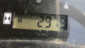
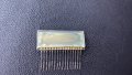
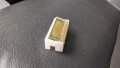
Hello all, I am in hopes your expertise can help me identify and possibly locate a supplier for an lcd. This lcd came off the instrument cluster of a small tractor. It's purpose is to show how many hours are on the tractor. There are no indentifying marks on this piece.

Attached are pictures of the lcd and of it in it's housing.

Thank you so much for looking at it. If there is any other information I can provide please let me know.
 

Attachments

jpanhalt

Joined Jan 18, 2008
11,087
That looks like a "DOG" (display on glass). It is probably made specifically for the tractor manufacturer. They are cheap even in relatively low volume.

It does have 16 pins, and the pinout is fairly standard for commercial character displays based on the Hitachi HD44780 driver, but I suspect that is unlikely. I don't see any controller attached to it. Is there a black blob of epoxy somewhere? If not, you are probably out of luck. You could buy a 16-pin bare display on glass and see what happens. They are cheap.
 

Thread Starter

Fish tree

Joined Sep 4, 2020
25
Thank you Janhalt. I pulled the instrument cluster back out, which is not easy to do. Attached are pics of the board. One pic of the entire front, then a close up pic of where the display goes. Then a pic of the entire back, with a close up of where the display goes. Please excuse the small solder splat. I accidentally did that when I was removing the display and haven't cleaned it up yet.

I do not see any epoxy.

Thank for informing me of the DOG. I am unfamiliar with this and need to do some research. The display, what I thought was an lcd, had a white backing on it. When I removed the white backing, the display just looked like a tinted piece of glass

This board is almost $500 so I am desperate to find an alternative.
 

Attachments

jpanhalt

Joined Jan 18, 2008
11,087
It looks like most of pins TP23 - TP38 go to the microcontroller in the middle. TP38 appears to make a few stops on the way, which would not be unusual if it controls something like a backlight or contrast.

What did the display look like? That is, was it drawn with small pixels or larger bars. Basically, could you tell whether it was a character display or graphical display? Did it have what looked like a factory design or mask? For example, a display on the dashboard of a car will often have a special design. If it was a simple character or graphical display, they may be hope of finding something that will work. If something special, the chances are dim.

This is what I mean by character display with large bars:
1599304667575.png

It is 16-pin and cheap: https://www.digikey.com/product-detail/en/orient-display/OD-6010/2544-OD-6010-ND/11698179#images Of course beside pin count, you also need to match dimensions. Even if both match, it will be a long shot.

Here's the original search term: https://www.digikey.com/products/en...dules-lcd-oled-character-and-numeric/99?k=lcd
 

Thread Starter

Fish tree

Joined Sep 4, 2020
25
It is definitely a character display, with large bars and simple characters from what I remember. I believe it had an hourglass symbol that would show on the left side, though. I will see if I can get a picture of one that is working and on, then post that so you can see exactly what it looks like.

That site you linked to seems like just the place I was looking for. I couldn't have found that on my own. Hopefully we can identify this piece. If so, this will be helpful to many people as others are also having this problem and I will do a write up on it.

I will post again as soon as I get the picture of the working display
 

jpanhalt

Joined Jan 18, 2008
11,087
The hour glass symbol may be special, but it may not be needed. Some of my implements have that just to show they are on.
 

Thread Starter

Fish tree

Joined Sep 4, 2020
25
Finally got a picture of an operating display. I don't think anyone would care if it was missing the hour meter. Hopefully the simplicity of this display increases the odds of finding one aftermarket. I really appreciate you offering your knowledge on this.
 

Attachments

jpanhalt

Joined Jan 18, 2008
11,087
Yep, that seems common on implements with hour meters. Looks like a 6-character display + special character. Like I mentioned earlier, pinouts follow a common pattern, but may not be exactly the same. One could probe the board with a logic probe or oscilloscope, but I doubt you have those tools. Thus, plugging something in has a risk, but that is considerably decreased if you can identify the power and ground pins to the display, which only requires a voltmeter. Power is probably 5 V or less.
 

Thread Starter

Fish tree

Joined Sep 4, 2020
25
You are correct, I do not have those tools. I do have a multimeter though. Might take me a little time but I should be able to locate those pins. I hate to ask, but do you any advice for the easiest way to do that? I was planning on hooking the board up and doing trial and error tests on the board where the display plugs in.
 

Thread Starter

Fish tree

Joined Sep 4, 2020
25
Ok, now I'm confused. When I used my meter on the board, with the machine running, I figured the outside two pins were ground and power, so I started with those. Tested 23 and 24 first, then tried 37 and 38. No reading. I did all sorts of combinations with each of the pins and never received a reading on my meter.

When I attached my meter's negative to the frame and I put my positive on the pinouts, each pin read 2.5 volts. They were all the same in this case.

What is going on?
 
Last edited:

jpanhalt

Joined Jan 18, 2008
11,087
Those displays are usually common anode or common cathode. This explains the difference: https://www.electronics-tutorials.ws/blog/7-segment-display-tutorial.html

In a common cathode anode display, the "com" pins are connected to ground. Power to each segment is provided by the driver pins (the MCU in your case). In the common anode display, the com pins are connected to a voltage and the MCU "sinks" (i.e., the pin to the segment is grounded/low by the MCU).

We don't know which type you have and the example I posted earlier my not ne relevant, but here's its pinout:

1599414019921.png

Making a big assumption, I would look at the traces and see if some of them (3 or 4 ) go to gnd or V+. Your display may be 4, 5, or 6 characters with decimal place for each. Seven segments + 1 decimal place = 8 which fits nicely for 8-bit micros (i.e., one byte).

Assume it is common cathode (if common anode just reverse polarities). If you were writing a "5" in the 1st digit, you need to turn on segments 1A,1F,1G,1C, and 1D. For a decimal point, you would also do 1P.

The MCU would pin1 to COM2 for (1A), pin1 to COM2 for 1C , pin1 to COM4 for 1D; then pin2 to COM2 for 1F and pin2 to COM3 for 1G . That would show the 5 segments needed for 5. The thing about LCD's is once a segment is turned on, it stays that way until cleared or written over.

If you can find the commons, whether positive or GND, then you will have a better guess as to whether the display might work. I am assuming no backlight. If there is a backlight, it will have its own pins. You usually do not need to turn the backlight on to see whether anything is on the display.

To reiterate, find the commons ("COM").

Just saw your new post: I'm stumped. I can understand all segment pins turning on at startup so all segments show. Maybe the MCU is working so fast that your meter doesn't show on/off states. Do you know anyone with an oscilloscope?
 

Thread Starter

Fish tree

Joined Sep 4, 2020
25
Uh oh, this is beginning to get over my head. I admire your intelligence on this matter. Unfortunately, I don't know anyone with an oscilloscope, or a better knowledge of this than myself. When the old display was in, I could see it dimly working. I believe the old display got burned up from the previous owner leaving the machine out in the sun. So, I feel positive the board works.

I'm going to think on it some, but at this point, I am tempted just to try a new display that has a typical pinout. I'm not sure what worse position I could be in to try, aside from being out a few dollars.

If I were to do that, should I try to find one on that site you linked to?
 

jpanhalt

Joined Jan 18, 2008
11,087
Uh oh, this is beginning to get over my head. I admire your intelligence on this matter. Unfortunately, I don't know anyone with an oscilloscope, or a better knowledge of this than myself. When the old display was in, I could see it dimly working. I believe the old display got burned up from the previous owner leaving the machine out in the sun. So, I feel positive the board works.

I'm going to think on it some, but at this point, I am tempted just to try a new display that has a typical pinout. I'm not sure what worse position I could be in to try, aside from being out a few dollars.

If I were to do that, should I try to find one on that site you linked to?
Sun or freezing are bad for LCD's. What model tractor? Does the manufacturer offer a refurbish service? (I once ended up buying a whole new heater control panel for a car - $600 -- for some little thing that broke and couldn't be repaired. I've been there. It's a bitter pill. ) TractorHouse.com lists sellers who are parting out equipment. Have you checked? Are you near Cleveland, Ohio?

As for a new just try it display, when you first started the tractor, how many characters came up? Just 4 or was it more? Since it is hours, I figure it has to be at least 5 characters.
 

Thread Starter

Fish tree

Joined Sep 4, 2020
25
I've checked for this as a used or refurbished part everywhere I can think of. It's only sold as an entire instrument cluster, which I understand, and the lowest price I've seen for it is $453, before taxes and shipping. It's from a 2006 John Deere x740. There are so many others people who have this problem it works help two fold if I could figure out how to replace only the lcd. I'm located in TN. Actually, I think the place I got that $453 quote was from a business listing on Tractorhouse.

When I started the machine, it wasn't visible enough to see how many characters came up. I'm thinking there would be six, based off the size of the display and the possible amount of hours that could be accumulated.

I feel certain this can be fixed if I could just find a replacement lcd. Unfortunately, I'm just not experienced enough to do it on my own.

I still have the instrument cluster apart, so I'll likely go test it again before putting it back together. Maybe there is something I missed. If there is anything else you think I should try I'm open to it. Also, if you happen across an lcd you think might work, I would like to check it out.
 

JohnInTX

Joined Jun 26, 2012
4,787
You sometimes can determine the pinout of a bare glass LCD as this looks to be with a multimeter set to the DIODE TEST mode. In that mode, the DMM will put enough voltage on the probes to excite the LCD. If the LCD is not totally shot with broken glass or leaking fluid, you might be able to use this procedure.
A segment turns on when there is a voltage coincidence between the backplane and a segment. LCDs can have more than one backplane to allow more segments with fewer pins. The table in #11 is an example of a 4 backplane LCD. The microcontroller generates all of the signals necessary to address each segment separately. Buzzing out the LCD with a meter simulates the signals one at a time.

  • Draw a table to put your results into. Label the rows COM0, COM1, COM2 and COM3.
  • This works with the LCD out of circuit.
  • Set up the meter in DIODE TEST. Short the leads momentarily to verify continuity. Number the pins on the LCD for your own reference.
  • Start with the black lead on pin 1. Drag the tip of the read lead over the remaining pins looking at the LCD (not the meter) and stop when you see a segment turn on. If none turn on, move the black lead to the next pin and repeat dragging the red tip over the remaining pins.
  • When a segment turns on, one lead is a backplane and one is a segment. To see which is which, continue running the red lead down the other pins. If you get multiple segments on in sequence, the black lead is a backplane. If no other segments turn on, the red probe was a backplane. Return the red probe to that pin and start your table:
  • Label the backplane pin COM0 and put the other probe on each of the other pins. Each one should light up a single segment or icon like the hourmeter. Record the results in the first line of the table.
  • If all segments have been accounted for and/or there are no unused pins, you have a single backplane "non-multiplexed" LCD and you know the pinout.
  • Otherwise, look for the next backplane. You will have one or more pins that are not in your table. Start with the black probe on one of those and again drag the red probe along the other pins. When one segment turns on, determine which probe is the backplane like before. It's likely that the red probe will be on one of the segment pins determined above, In that case the black probe is another backplane. Label it COM1 and fill in the table as before by touching each of the other pins (you can omit COM0) and logging which segment turns on.
  • Continue until you have found all the backplanes (no more pins) and the table should look like the one above.
  • The number of rows is the number of backplanes and that is the primary spec for looking for a replacement. Shop for a pinout and segment table that is most similar and see if you can wire around differences by comparing your pinout table with the display's datasheet.

Most displays will work at least a bit with a meter. You can also use a couple of AA batteries in series for 4.5V, a 9V battery or scab some DC from a wall-wart as a last resort (check the voltage). LCDs do have a max voltage rating but you're just poking around at this point and should be OK with any of those.

Kind of a hail-mary but give it a shot.
Good luck!

EDIT: the white sticker that TS pulled off is the reflector. Put it back on to see the segments better. Be sure you haven't pulled off the polarizer (gray plastic sheets on each side of the glass). The LCD needs both polarizers to show anything.
EDIT2: re: wiring around differences. The pins can be different but the assignment of segments and backplanes must be the same. You can have unused segments in the new one, that's OK.
 
Last edited:

jpanhalt

Joined Jan 18, 2008
11,087
Well, you probably know that JD is one of the prime targets for the "right to repair" contingent. Its 35 HP to 45 HP CUT's are all the same except for the engine's computer program, or so I have heard. Mine's a Case (CNH, Canada) of the same class. Of course, if the tractor still runs, that LCD is not needed. But, I am with you. All of the hour meters on my equipment work and run all the time.

Search around. Find some LCD you think might work. Post it here. I and others will look at it. You have nothing to lose. If that fails, offer $350 + shipping. Nothing ventured nothing gained.

Whatever you do, remember there may be a problem setting the run time to the current, correct value. I keep a log book for all (4) of my implements.
 

Thread Starter

Fish tree

Joined Sep 4, 2020
25
I've been testing pins. I can get a small flicker from time to time, but it's in bad enough condition that segment will not stay lit.

From left to right, I can get a segment to light up when I have a lead on pin 1, and the other on lead 7, 8 or 11. There might be others that should work but they just aren't showing up because of the condition.

That was actually kind of a fun little test. I'm not sure what it tells me though.

I have read about JD right to repair issues. I can't say I disagree with the farmers. They are spending a lot of money on the machines. There are risks associated with repairing their own but haven't people been repairing their own vehicles since the first car rolled off the line?

I'm thinking the brains of this part are on the board so maybe it will show the correct value if I can get a display to work. If not, I can write the current hours in the manual and on the cluster itself. I have dealer records and based off that, the dealer estimates it to have 800 hours, so I have that as a reference just in case. The previous owner said that should be very close, too.

My wife and kids are out of town today or I wouldn't have had all this time to work on this!
 

jpanhalt

Joined Jan 18, 2008
11,087
I agree. Keep a log of every implement you have. I keep one as religiously as an airplane log. Every oil change is noted. For my mower, I grease every 8 hours and don't document that. For my other stuff, I do. Lack of a real time clock is a problem for a low time machine. After 2000 hours it becomes less important.

Good luck. If you buy something that "looks about right," I think the probability for screwing the MCU is pretty slim even if it doesn't work.
 

Thread Starter

Fish tree

Joined Sep 4, 2020
25
Thank you so much. You have a been a great help and this has been a nice lesson for me. If I find a display should I post it here or start a new thread?

I looked at another site and found the same lcd you mentioned at the top of this post. It's out of stock so I emailed them to see if there is a replacement part.
 
Top