 Facebook
 Google
 GitHub
 Linkedin
Hi all,
Its me again. I know i'm like a stray cat right? So here's my problem in the best way I can explain it. I have a 4x20 LCD attached to an arduino. The arduino is attached to several components including an eight channel solid state relay board which drives 24VAC and one relay for 120VAC. Everything runs great for a little while. (I say little while cause this issue doesn't happen at the same time interval, its random. So to specify we'll say anywhere from 15 minutes to 2 hours.) After a "little while" the LCD goes nuts and displays very odd characters. I've googled and googled and read page after page trying to weed out my issue but my efforts are inconclusive.
From what i've looked on google I've tried the following but will be more then willing to try again if suggested. Heres what i've tried so far:
1. Adding filter capacitors (Ceramic capacitors values .01 to 1uf)
2. Adding "support" capacitors (Electrolytic capacitors values 47 to 220 uf)
3. Adding a diode to ground to prevent rouge signal traveling up the ground wire
4. I've looked through every line of my code to find any bit that might confuse the LCD.
5. I added a 1000uf capacitor to my main power rail on my breadboard.
As of right now I have both 1&2 still in place along with #5. I removed the diode and the code from my POV is completely ok.
I know what your thinking, the relays right? I would think so too if they weren't isolated using phototriac isolation. If I did my research correctly its using a emitter LED with a IR receiver to know when to switch the relays. The relays are also on their own branch off the power supply. Not directly hooked to the arduino except the signal lines. Thus being said, they are connected only through the main power to the relay board, and the ground wire to the relay board itself. Which I have filter capacitors going after and before this connection.
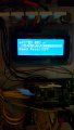
I've attached a image to give an example of whats going on. The LCD text is perfect when it first starts running and I've activated the relays one by one to check for a bad connection but it never does it until its ran for a while. I dunno what to try next so this is my calling for any advice you may have.
As always thank you for taking the time to read this even if you don't post a reply. I know its a long post.
- M
EDIT: Sorry, Attached a wiring diagram as well.
Its me again. I know i'm like a stray cat right? So here's my problem in the best way I can explain it. I have a 4x20 LCD attached to an arduino. The arduino is attached to several components including an eight channel solid state relay board which drives 24VAC and one relay for 120VAC. Everything runs great for a little while. (I say little while cause this issue doesn't happen at the same time interval, its random. So to specify we'll say anywhere from 15 minutes to 2 hours.) After a "little while" the LCD goes nuts and displays very odd characters. I've googled and googled and read page after page trying to weed out my issue but my efforts are inconclusive.
From what i've looked on google I've tried the following but will be more then willing to try again if suggested. Heres what i've tried so far:
1. Adding filter capacitors (Ceramic capacitors values .01 to 1uf)
2. Adding "support" capacitors (Electrolytic capacitors values 47 to 220 uf)
3. Adding a diode to ground to prevent rouge signal traveling up the ground wire
4. I've looked through every line of my code to find any bit that might confuse the LCD.
5. I added a 1000uf capacitor to my main power rail on my breadboard.
As of right now I have both 1&2 still in place along with #5. I removed the diode and the code from my POV is completely ok.
I know what your thinking, the relays right? I would think so too if they weren't isolated using phototriac isolation. If I did my research correctly its using a emitter LED with a IR receiver to know when to switch the relays. The relays are also on their own branch off the power supply. Not directly hooked to the arduino except the signal lines. Thus being said, they are connected only through the main power to the relay board, and the ground wire to the relay board itself. Which I have filter capacitors going after and before this connection.
I've attached a image to give an example of whats going on. The LCD text is perfect when it first starts running and I've activated the relays one by one to check for a bad connection but it never does it until its ran for a while. I dunno what to try next so this is my calling for any advice you may have.
As always thank you for taking the time to read this even if you don't post a reply. I know its a long post.
- M
EDIT: Sorry, Attached a wiring diagram as well.
Attachments
-
 111.4 KB Views: 19
 -
 436.8 KB Views: 19


