LCD driver

Thread Starter

Ally Cat

Joined Mar 28, 2016
78
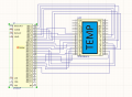
I am trying to hook up VI-302-DP-RC-S to AY0438-I/P. There is 4 digits capable in the Chip Driver and 3.5 in the LCD. I am having difficulty in material provide for these parts. I am confused in the how to set up K and Com to the VI 302-DP-RC-S. The same schematics show this going to GPIO. The documentation on the driver is vague. I am expecting a resistor going to a ground on this design on the LCD.
 

Attachments

Travm

Joined Aug 16, 2016
363
Do you have a datasheet for the display?. Not finding much online.

Found it, looking at it now.
 
Last edited:

Travm

Joined Aug 16, 2016
363
Reading the two datasheets, the com pins connect to the backplane pin on the driver, and k connects to your choice of segment pins, it relates to the .5 digit. I don't believe there is any resistor, but I also didn't read the entire driver datasheet.
Page 4 of the datasheet shows the connections. Com pins are also called backplane.
 

Thread Starter

Ally Cat

Joined Mar 28, 2016
78
Thanks Where does the com need to connected to on the LCD driver. Give me a sec to up load the data sheets
 

Thread Starter

Ally Cat

Joined Mar 28, 2016
78
I see there is back plane version on the driver. The reference schematic does not show how the LCD pin is used. It just has a filer cap on it.
 

Analog Ground

Joined Apr 24, 2019
460
I see there is back plane version on the driver. The reference schematic does not show how the LCD pin is used. It just has a filer cap on it.
The capacitor on the LCD pin sets the frequency of the waveform driving the LCD segments. There is a graph on the data sheet showing the frequency vs capacitor value. If the frequency is too low, the segments might appear to "flicker".

Edit: A typical value would be 100 Hz. The capacitor is 40 pF for 100 Hz.
 
Last edited:

Analog Ground

Joined Apr 24, 2019
460
Thanks Where does the com need to connected to on the LCD driver. Give me a sec to up load the data sheets
Connect both COM pins on the LCD to the BP output of the controller. These are NOT ground pins. They are backplane connections to the LCD. THere are not ground or power pins on an LCD display of this type. Just backplane and segment connections.
 

Analog Ground

Joined Apr 24, 2019
460
One issue is what to do with the LCD segments you don't want to use. For example, K, X, Y and Z are not connected on the schematic. My thinking is connect these to unused outputs on the controller and never turn them on. Always set the corresponding bits in the control register to "off". These means they will be correctly driven with an AC waveform which might be important for overall operation and reliability of the display.

Edit: Also the "L" segment. The NCx pins are no connects. Leave them open or not connected to anything.
 
Last edited:

BobaMosfet

Joined Jul 1, 2009
2,113
From a datasheet on mouser, this shows pins connected or not connect:

1591033344343.png
Be aware, that this is NOT a DC device. It requires a pulsed wave-form, at least 32Hz. The correct way to power the segments (most easily) is by either using an AND gate, or doing the gate in logic in the MCU.

One input to the AND gate is the 32Hz clock pulse, and the other input is the segment on/off pulse. As long as the segment on-off pulse is high, the output of the AND gate will be high when the clock-pulse is high. If you drive this display with a steady DC output, you will ruin it, as it will damage it over time.
 

Thread Starter

Ally Cat

Joined Mar 28, 2016
78
I was not aware of this AC. I am still confused. Are are you talking about the driver or LCD. My understand is I just define the bits in the driver register and it handles the LCD. Please tell me error in my logic.
 

Thread Starter

Ally Cat

Joined Mar 28, 2016
78
The example you sent is for direct connection to the LCD. I have a driver in my design. Does the driver handle all this?
 

JohnInTX

Joined Jun 26, 2012
4,787
Be aware, that this is NOT a DC device. It requires a pulsed wave-form, at least 32Hz. The correct way to power the segments (most easily) is by either using an AND gate, or doing the gate in logic in the MCU.
One input to the AND gate is the 32Hz clock pulse, and the other input is the segment on/off pulse. As long as the segment on-off pulse is high, the output of the AND gate will be high when the clock-pulse is high. If you drive this display with a steady DC output, you will ruin it, as it will damage it over time.
The AY0438 LCD driver generates the AC signals necessary to drive the LCD so don't worry about all of that. The frequency is set by the value of the capacitor on pin 31 (LCD Φ). The capacitor selection is shown in Fig5. Pick a freq. somewhere in the middle.
The LCD panel has the single backplane (COM) supported by the AY0438 driver (BP) so you're good to go there.
You should hook up the segments in some easy to map arrangement to create the digits and symbols but you don't have to if it makes the PCB layout easier. You turn segments on and off by shifting 32 bits to the internal shift register in the AY0438.
The firmware will determine the digit segments to display(0-9, other patterns), the digit location and convert that to bits within the 32 bit shift register to turn on the segments to show that digit. Each segment in each digit plus decimal points and symbols will have one corresponding bit (Seg1-Seg32) in the shift register. Note that corresponding segments in different digits have different drive bits in the 32 bit shift register.
The hookup suggestions by @Analog Ground are valid. You can also connect unused segments to the backplane.
That's about all there is to it.
Good luck!
 
Last edited:

BobaMosfet

Joined Jul 1, 2009
2,113
I was not aware of this AC. I am still confused. Are are you talking about the driver or LCD. My understand is I just define the bits in the driver register and it handles the LCD. Please tell me error in my logic.
I was talking about the LCD. They are very easy to control.
 
Top