LC Filter circuit (Acceptor Rejector) HELP!!

Thread Starter

Jermain93

Joined Mar 23, 2016
7
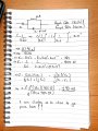
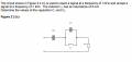
The circuit shown in Figure 2.2 (c) is used to reject a signal at a frequency of 6kHz and accept a signal at a frequency of 2kHz. The inductor L1 has an inductance of 8 mH Determine the values of the capacitors C1 and C2.

Im stuck on this question, I have managed to find C1 and I will attach an image of my working out so far.

any help would be much appreciated.
 

Attachments

MrAl

Joined Jun 17, 2014
11,389
Hi,

Did you make a mistake with that -j*90.48 number?
That does not look right because of the denominator sign to the left of that.
Check the sign of the capacitance.

Check that first.

The next idea after that would be to try to get the through (series) impedance at low as possible at 2kHz by choosing the right value for C2. Once you get the right answer above i believe that will be very easy.

Intuitively, the parallel section is high impedance for the resonant frequency but as the frequency goes down from that value the capacitor becomes less effective and the inductor more effective, thus the parallel combination should look mostly inductive which implies a certain sign for the impedance result at 2kHz (namely, positive).
 
Last edited:

WBahn

Joined Mar 31, 2012
29,978
What qualifies as accepting and rejecting a signal? We can't tell since you only give a circuit snippet that doesn't indicate what the signal even is. Is it a current? If so, which current? A voltage? If s, which voltage?
 

MrAl

Joined Jun 17, 2014
11,389
What qualifies as accepting and rejecting a signal? We can't tell since you only give a circuit snippet that doesn't indicate what the signal even is. Is it a current? If so, which current? A voltage? If s, which voltage?

Hi there,

Because there are no resistances in this circuit, i believe that if you work the problem a little you'll soon find out that this is one of those idealistic circuits and so has an idealistic solution. I didnt want to give too much away though so i stayed rather vague in my reply, but a little thought about how these kinds of ideal filter circuits work and maybe a few small calculations will show what they are looking for. It's super simple, but has to be viewed as such to see what's being sough after. What i dont know is if the OP understands this kind of simplistic thinking. I was waiting for a reply first.
 

WBahn

Joined Mar 31, 2012
29,978
Oh, it's certainly an ideal infinite impedance, zero impedance type circuit. But the TS needs to learn to describe what they are trying to achieve.
 

Thread Starter

Jermain93

Joined Mar 23, 2016
7
Hi,

Did you make a mistake with that -j*90.48 number?
That does not look right because of the denominator sign to the left of that.
Check the sign of the capacitance.

Check that first.

The next idea after that would be to try to get the through (series) impedance at low as possible at 2kHz by choosing the right value for C2. Once you get the right answer above i believe that will be very easy.

Intuitively, the parallel section is high impedance for the resonant frequency but as the frequency goes down from that value the capacitor becomes less effective and the inductor more effective, thus the parallel combination should look mostly inductive which implies a certain sign for the impedance result at 2kHz (namely, positive).
does the -j^2 on the numerator divide with the j on the denominator and leave you with one -j?
 

Thread Starter

Jermain93

Joined Mar 23, 2016
7
Hi,

Did you make a mistake with that -j*90.48 number?
That does not look right because of the denominator sign to the left of that.
Check the sign of the capacitance.

Check that first.

The next idea after that would be to try to get the through (series) impedance at low as possible at 2kHz by choosing the right value for C2. Once you get the right answer above i believe that will be very easy.

Intuitively, the parallel section is high impedance for the resonant frequency but as the frequency goes down from that value the capacitor becomes less effective and the inductor more effective, thus the parallel combination should look mostly inductive which implies a certain sign for the impedance result at 2kHz (namely, positive).
oh im missing a minus sign, thanks, must have overlooked it.
 

MrAl

Joined Jun 17, 2014
11,389
Hi,

You're welcome...

Once you get that the rest will reveal itself, but if you still have a problem just yell right here :)

Here is an approximate graph of the filter transfer characteristic once we choose the right values and if we used it as a filter with some resistive output impedance. Note the negative peaks go down lower but can not be graphed to minus infinity so they just show up as very low level signals
The 'y' axis is in db while the 'x' axis is in Hertz..

CLC_FilterTranferCharacteristic-1.gif
 

WBahn

Joined Mar 31, 2012
29,978
here is the full actual question
Thanks. That circuit makes it pretty evident that the input signal is a voltage applied across the left hand terminals and the output signal is the voltage across the resistor. That is not at all evident from just the branch you showed in your first post.
 

RBR1317

Joined Nov 13, 2010
713
Looking at the Bode magnitude plot for a range of values of load resistance, it is apparent that the low-pass accept notch is not very pronounced except for R<100Ω.
accept-reject-filter.png
 

Thread Starter

Jermain93

Joined Mar 23, 2016
7
Hi,

You're welcome...

Once you get that the rest will reveal itself, but if you still have a problem just yell right here :)

Here is an approximate graph of the filter transfer characteristic once we choose the right values and if we used it as a filter with some resistive output impedance. Note the negative peaks go down lower but can not be graphed to minus infinity so they just show up as very low level signals
The 'y' axis is in db while the 'x' axis is in Hertz..

View attachment 103034
thanks MrAl, i will attempt to complete it later today, i think i know what i am doing now :)
 

MrAl

Joined Jun 17, 2014
11,389
thanks MrAl, i will attempt to complete it later today, i think i know what i am doing now :)

Hi again,

Jermain:
You're welcome.
You might also remember that the sum of two impedances might equal zero if they cancel each other out at a particular frequency.

RBR1317:
Yes, but unfortunately we dont have any control over that because C1 is locked in with the value of the inductance, and C2 is locked in with the value of C1 and the inductance, so the only way we can control the circuit Q is with the inductor, but we are not allowed to change that yet, and the resistance is unspecified.

To make this more clear, the transfer function in terms of the locked in values for C1 and C2 is:
Vout(s)/Vin(s)=(s*(w6-w2)*(w6+w2)*(w6^2+s^2))/(w2^2*w6^4*LR+s^2*w6^4*LR+s*w6^4-s*w2^2*w6^2+s^3*w6^2-s^3*w2^2)

and here LR=L/R, so the only way we can change the circuit Q if R changes is to change the inductor value.
Note nothing else changes when we change either the inductor L or the resistor R because the two frequencies w2 and w6 are constant.
If you care to you can solve for the circuit Q iin the passband with that transfer function.
 

RBR1317

Joined Nov 13, 2010
713
...so the only way we can control the circuit Q is with the inductor, but we are not allowed to change that yet, and the resistance is unspecified.
Yet in order to do a Bode plot the resistance must be specified. So I specified it as a parameter. The only reason for posting the Bode plot was to eliminate the gotcha that if you see no peaking in the passband, as would be expected, then the resistance is too high.
 

MrAl

Joined Jun 17, 2014
11,389
Hi,

That's interesting too, but if you solve for the Q you should end up with a formula for that which will involve R.
But then again, who is to say that a broad bandwidth isnt what was wanted. In other words, if we cant change R then we have to go with whatever becomes of it :)
In any case, the Q will reveal the nature of the passband response for any R. Of course a Q if 1 isnt that sharp, while a Q of 10 is sharper, etc., and this would be based on the value of L and R so we could probably do a plot of the Q vs R for example given the fixed L.
But it is good to know that it is not always going to be sharp, depending on the value of the load.
 

MrAl

Joined Jun 17, 2014
11,389
Hi,

I had went ahead and solved for the Q of the circuit but the solution came out a little too complicated to make it worthwhile to post here, so instead i just graphed the solution. As you can see, it came out interesting because it's a straight line relating the ratio L/R to the circuit Q.
As you can also see, the Q increases with increasing L and this is typical with these circuits.
As RBR alluded to previously, the Q goes down with increasing R.

I would post the solution but it's too long to make it practical, so here is the graph which is much more interesting, and we can then easily come up with an empirical solution if needed, which would also suggest there is a simplification.

For one example using the graph, if L=0.010 and R=1 then the Q is about 175.
For L=0.008 and R=1 (or L=0.080 and R=10 for example) the Q is about 127 but might be a little hard to read that on the graph although it can be approximated anyway.


Qplot-CLC_Circuit-1.gif
 
Top