I have an optic fibre lamp (basically a bunch of optic fibres in a base with 4 LEDs in it), it came with 4 blue LEDs which were rather unexciting, so I simply swapped them for 4 slow animating RGB LEDs. The effect was impressive, because the LEDs get out of sync and so each part of the optic fibre bundle is a different colour at any one time, depending on the colour of the LED directly below it, and the other LEDs as well, which mix into the colour somewhat.
Generally, these LEDs shift between each colour every 5-7 seconds, so sounds like what the OP wants. It's by far the simplest, most effective way to make a lamp interesting, and all it takes is four RGB LEDs and four 180 ohm resistors (if the supply is 5V, higher for higher voltages of course).
The OP's original board has 9 LEDs, but really you can use as many as you like, although with too many, the colours will mix so much that the effect can actually be less interesting. I would start with four and if not bright enough, add a few more.
Re the OP's original board, I would say the IC is a micro, as others have stated, and the number is an in-house number, so means nothing outside the manufacturer's system. It's common for Chinese-made gear to have components with in-house numbers or no numbers at all.
If the package uses a clocked processor it may be useful to simply slow the clock. So in that case just putting another capacitor in parallel with the timing pulse generator capacitor will slow things down. Not serious high science. Determining the amount to slow it enough may be a bigger challenge. And it may be that it would slow other functions as well and not be what is intended.
But it is cheap and easy to try.
I recommend building your own lamp with a microcontroller. An Arduino Uno would work with minimal wires to deal with.
I made two lamps that use the ATtiny85 microcontroller. The first design is nothing more than a RGB led and the microcontroller with series resistors for each colour.
I made a second version that uses transistors to power an array of LEDs. Both versions have a socket so the 8 pin chip can be reprogrammed.
What I did is basically what's happening with your lava lamp. You could find out which wires are for the LEDs and use an Arduino Uno to write your own patterns. I use the EEPROM and a single switch to allow for different modes. The possibilities are endless.
It is indeed rather complicated. three transistors and seven resistors and at least one diode, plus a filter capacitor.
That IC undoubtedly is hard programmed and not likely to be able to be changed.
The back side of the circuit board may hold additional components, but maybe not.
So the next thing would be to watch the LEDs as the program runs. Thenyou will have some idea as to what the present control actually does. The LEDs nay vary in brightness rather than just switch on and off.
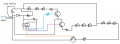
I count 9 LEDs labeled R,G,B three each so my guess id the three colors are Red, Green, Blue. I count three transistors so likely the three transistors are driving three LEDs each. Best guess is I agree the chip an 8 pin DIP chip is likely a uC (micro-controller) coded to digital out three channels driving the three transistors with a delay of 2 seconds for each channel. Less seeing the actual schematic it's hard to guess exactly what that "ball game" chip actually is. Yep, less any part number on the top of the chip it's pure speculation.
Hi, thank you for your reply. Yes it seems so. I tried drawing a schematic myself (I am really a beginner at this), and do you think there's any chance you can somehow figure out what chip could be used for the same purpose in this scenario?
I recommend building your own lamp with a microcontroller. An Arduino Uno would work with minimal wires to deal with.
I made two lamps that use the ATtiny85 microcontroller. The first design is nothing more than a RGB led and the microcontroller with series resistors for each colour.
I made a second version that uses transistors to power an array of LEDs. Both versions have a socket so the 8 pin chip can be reprogrammed.
What I did is basically what's happening with your lava lamp. You could find out which wires are for the LEDs and use an Arduino Uno to write your own patterns. I use the EEPROM and a single switch to allow for different modes. The possibilities are endless.
Here, I tried making a schematic (I am really a beginner lol). Does this tell you anything that could be helpful?
Like, I know I am a beginner. But shouldn't it be possible to find a microcontroller and just replace it by this point, that simply fades the colors slower?
So this is possible by this point? I mean, I just don't have the knowledge of the different pin outputs and their meaning. So idk how I would connect it. Do you know anything?
Well you would need to become familiar with micro processor application and programming, three designated outputs needed at least, the 8 pin has 6 programmable pins.
I recommend building your own lamp with a microcontroller. An Arduino Uno would work with minimal wires to deal with.
I made two lamps that use the ATtiny85 microcontroller. The first design is nothing more than a RGB led and the microcontroller with series resistors for each colour.
I made a second version that uses transistors to power an array of LEDs. Both versions have a socket so the 8 pin chip can be reprogrammed.
What I did is basically what's happening with your lava lamp. You could find out which wires are for the LEDs and use an Arduino Uno to write your own patterns. I use the EEPROM and a single switch to allow for different modes. The possibilities are endless.
I don't think I am going to try do everythign from scratch, other than try to simply find another chip and make it the way I want according to this circuit board. But, regarding your project and mine; do you see any possibillity to create that with this schematic I made from the lamp? (I am a beginner so this may look really bad but here it is)
Well you would need to become familiar with micro processor application and programming, three designated outputs needed at least, the 8 pin has 6 programmable pins.
I saw some on YouTube, where some dude talks about basic programming and stuff. It looked like I could follow what he did. But I am just worried I am not going to manage with the outputs and the coding. With that I would still need help.
Your schematic is clearly wrong, but is close enough to get the primary gist across. From this we can determine which pins on the MCU are the power and ground (and probably the master reset) and which pins are the signal outputs. But we need to know which pin is pin one. Which side of the MCU is located next to the white wire?
But after picking a replacement MCU, you have to write the program for it and then you have to program it. Both of these are pretty simple tasks, but there is both a learning curve associated with them and some equipment you need to get. So unless you know someone that is willing to do that for you or you are interested in doing it yourself because you have other projects in mind that those skills would be useful for, you need to decide whether this is important enough to you to pay someone to do it for you.
Oh, can you tell what makes it wrong? Maybe I can change it.
If you are referring to my schematic, regarding where the pin one is, then it's the one on the top left. If you want a clearer image taken with camera then I can provide that as well.
I am willing to do this myself, money isn't a problem at all. I just want to make sure I find someone that could help me with coding etc. Soldering etc is not a problem for me.
So is your schematic showing a bottom view of the MCU? Convention is to show it from the top side, in which case pin 1 will either be the lower-left or the upper-right.
So is your schematic showing a bottom view of the MCU? Convention is to show it from the top side, in which case pin 1 will either be the lower-left or the upper-right.
 Facebook
 Google
 GitHub
 Linkedin