 Facebook
 Google
 GitHub
 Linkedin
Hello! I started this thread: https://forum.allaboutcircuits.com/...-laundry-machine-shutoff-switch-relay.193432/ a little over a year ago. We are finally getting back to work on it.
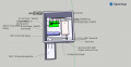
To recap - our washing machine drain line plugs from time to time and floods the room. My son and I designed a control circuit that would sense the rising level in the pipe via a float and switch and shut the power off to the washing machine before the machine empties itself onto my floor.
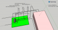
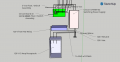
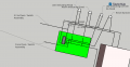
In the original thread, I was asked to post diagrams for critique, so here they are. I am using an 8" x 8" Square PVC control box attached to a PVC receptacle box. The control box houses a Circon CFM40T-02 Switching Power Supply, our circuit board with a SN74LS02 IC and an Altech Corp 8905.2 relay. We have set the IC up as an SR Latch, which activates the relay, opening the 120 volt stopping the washing machine when the float switch closes. On the bottom of the box is a fused Power Inlet that will plug into the GFCI wall receptacle to provide power to the electronics and the washing machine. Indicator lights, an audible alarm, and the reset button and a reset button will be on the top.
My Questions:
1) I plan to put a 15 Amp Fuse in the power inlet. Is that adequate for the entire unit, or should I have something smaller on the circuit board?
2) I think I need to use the NC side of the relay, not the NO side, can someone confirm?
3) Do I need to / is there a way to ground the DC side of the Power Supply?
4) The CFM40T-02 (Datasheet Here) uses "industry standard" pinout that does appear to have a connection for 14 AWG Copper wire. Is there a piece I am missing?
5) The original feedback suggested a ruggedized design - I think this fits the bill, but again, I am open to feedback.
6) Anything I may be forgetting....
To recap - our washing machine drain line plugs from time to time and floods the room. My son and I designed a control circuit that would sense the rising level in the pipe via a float and switch and shut the power off to the washing machine before the machine empties itself onto my floor.
In the original thread, I was asked to post diagrams for critique, so here they are. I am using an 8" x 8" Square PVC control box attached to a PVC receptacle box. The control box houses a Circon CFM40T-02 Switching Power Supply, our circuit board with a SN74LS02 IC and an Altech Corp 8905.2 relay. We have set the IC up as an SR Latch, which activates the relay, opening the 120 volt stopping the washing machine when the float switch closes. On the bottom of the box is a fused Power Inlet that will plug into the GFCI wall receptacle to provide power to the electronics and the washing machine. Indicator lights, an audible alarm, and the reset button and a reset button will be on the top.
My Questions:
1) I plan to put a 15 Amp Fuse in the power inlet. Is that adequate for the entire unit, or should I have something smaller on the circuit board?
2) I think I need to use the NC side of the relay, not the NO side, can someone confirm?
3) Do I need to / is there a way to ground the DC side of the Power Supply?
4) The CFM40T-02 (Datasheet Here) uses "industry standard" pinout that does appear to have a connection for 14 AWG Copper wire. Is there a piece I am missing?
5) The original feedback suggested a ruggedized design - I think this fits the bill, but again, I am open to feedback.
6) Anything I may be forgetting....
Attachments
-
 90.4 KB Views: 9
 -
 65.9 KB Views: 9
 -
 72 KB Views: 8
 -
 69.4 KB Views: 8


