 Facebook
 Google
 GitHub
 Linkedin
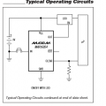
Hi Guys! I am making a latch circuit where i have a push button,MAX16054 IC, enable LDO IC AP2112 and ESP32 that operates at 3v3. Ok now i want to make latch circuit functionality bery similar to that of MP3 player where ON Long press you turn OFF and ON the device.There maybe other sorts of devices that you may be familiar with that follows the same functionality. I want to configure my circuit in such a way that when i long press the button for approximately 3 sec, MAX16054 will latch enable pin of LDO that would then output 3.3V to Esp32. I am supplying 5V from the battery to VCC of MAX16054 and to Vin of LDO. This is what i want to achieve but the problem arises in the push button. I have used 555 timer next to push button but it adds delay issues when i add modes to my MCU. Thats why timer IC is not recommended here.I tried with RC circuit but still no good. I hope someone would read it and give some solution...thanks
I have added a picture that would be very helpful
I have added a picture that would be very helpful
Attachments
-
 12.1 KB Views: 31


