Facebook
 Google
 GitHub
 Linkedin
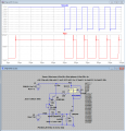
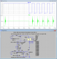
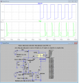
Here are the results using different cap values at the base of Q2...OK, I had not thought about startup conditions. Sorry about that. And it was a quite small capacitor, just enough to reduce the frequency response. to avoid the oscillation.. Now a question: I have designed, and our company built and sold a bunch of them, devices for measuring speed based on an object breaking two laser beams in sequence, and accurately measuring the time between breaks. Each unit utilized 4 ready-made laser assemblies, usually 2 or 3 milliwatts. On the opposite side were 4 sensors, first we used the Honeywell digital sensors, then the Fairchild ones. Fairchild sensors have a real problem with the location of their sweet spot, which causes all kinds of problems. Those original laser devices are now at least 15 years old, and the lasers no longer are quite as bright. Are you designing small laser devices to be sold to OEMs??
Attachments
-
 44.5 KB Views: 20
 -
 41.8 KB Views: 16
 -
 43.6 KB Views: 18