Laser diode driver oscillating output

Thread Starter

fdc2k17

Joined May 15, 2017
29
Hi,
I came across a circuit which can be used to drive a laser diode in continuous mode (CW) or modulated (<=100Khz).
A BFR540 (NPN) transistor is used to drive the laser diode and a photodiode (inside the laser diode package) provides an output current based on the optical output power, which is used as a feedback to control the optical output power. The latter is set via the potentiometer at the base of the BFT93 (PNP) transistor. Modulation, when needed, is achieved by switching the MOD line between 3.3V and GND.

The circuit is shown in the attachment.

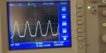
As shown, it works correctly. HOWEVER, when I change the BFT93 (PNP) to any other PNP transistors, the output (laser power) oscillates at high frequency (>1MHz). The reason I'm having to change the BFT93 is that this part is now obsolete and hard to get.
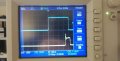
If I increase the value of the capacitor at the base of BFR540 the system becomes stable, but I cannot modulate it at 100 KHz anymore.

I believe that this oscillation will be due to the poles and zeros of the closed loop being inappropriate, but I'm not sure how to find the required information from the circuit.

I would appreciate if anyone could provide any advice/suggestions. I think I gave all the information I can about the circuit and its behavior, but if more information is required please let me know.

NOTE: I have tried replacing the BFT93 with transistors which have the closest parameters (i.e. hfe, Vce, power, etc), but I couldn't find any that matched the frequency (5GHz).
 

Attachments

Dodgydave

Joined Jun 22, 2012
11,301
Why don't you omit the BFT93, and use a Constant Current supply for the laser diode, like a LM317 , then you can modulate it with the BFR540 and set the current with the LM317 ?
 

Thread Starter

fdc2k17

Joined May 15, 2017
29
Why don't you omit the BFT93, and use a Constant Current supply for the laser diode, like a LM317 , then you can modulate it with the BFR540 and set the current with the LM317 ?
Hi,

Thanks for your suggestion.
I forgot to mention that I need the laser to have stable output independent of changes in ambient temperature (to some level).
I had initially implemented a similar approach to what you suggest, but the output would vary with a simple blow of air.
Therefore I found that using the built-in photodiode would help me achieve this goal. The photodiode has a much more stable temperature coefficient, which means that its properties are less affected by temperature.

As I mentioned in the initial thread...with the BFT93 the system works correctly. It is only when I replace it with some other transistor (also PNP) that the output starts oscillating, and I don't know why. I have a hunch, but that is all at the moment.
 
Last edited:

Dodgydave

Joined Jun 22, 2012
11,301
The reason is probably the substitute transistor hasn't got the frequency response of the BFT93.

I would still go with a Constant Current source, and modulation as normal.
 

ronv

Joined Nov 12, 2008
3,770
Hi,

Thanks for your suggestion.
I forgot to mention that I need the laser to have stable output independent of changes in ambient temperature (to some level).
I had initially implemented a similar approach to what you suggest, but the output would vary with a simple blow of air.
Therefore I found that using the built-in photodiode would help me achieve this goal. The photodiode has a much more stable temperature coefficient, which means that its properties are less affected by temperature.

As I mentioned in the initial thread...with the BFT93 the system works correctly. It is only when I replace it with some other transistor (also PNP) that the output starts oscillating, and I don't know why. I have a hunch, but that is all at the moment.
What are you trying to replace it with?
Maybe this one?
https://www.mouser.com/datasheet/2/308/MMBTH81-1301429.pdf
 

Thread Starter

fdc2k17

Joined May 15, 2017
29
What are you trying to replace it with?
Maybe this one?
https://www.mouser.com/datasheet/2/308/MMBTH81-1301429.pdf
That is one of the transistors I tried replacing it with. Unfortunately, it did not work.
I tried all PNP transistors I could find that had the highest frequency possible. however, none were above 600MHz.
What I don't understand is why would this circuit require such high frequency transistors to work in the first place.
Any ideas?
thanks
 

Thread Starter

fdc2k17

Joined May 15, 2017
29
The reason is probably the substitute transistor hasn't got the frequency response of the BFT93.

I would still go with a Constant Current source, and modulation as normal.
I would, if variation due to temperature wasn't critical. With the design proposed you'd have one power output in summer and a completely different one in winter, and that's not even accounting for the influence of temperature in the constant current source.
The frequency response is my hunch, however, how do I extract the frequency response of the individual parts of this circuit in order to work out what is the minimum frequency response required for the transistor in question?

thanks.
 

ronv

Joined Nov 12, 2008
3,770
Just thinking out loud....
I think you may need to break the high frequency from the low frequency (temperature).
So the average feedback can be slow(er).
I had a similar need in a rewritable optical disk drive. Give me some time to try to remember - it was a long time ago. :)
What is the output voltage of the photo diode?
 

MisterBill2

Joined Jan 23, 2018
18,463
My suggestion is t reduce the frequency response of the feedback that is holding the output constant. Try a capacitor between base and emitter of the substitute PNP that is replacing the BFT93. Usually oscillation at such high frequencies is caused by excess gain at those frequencies. That transistor is not an active part of the modulation process, it is there to compensate for temperature changes. So a lower speed device should be suitable. At least that is what it looks like to me.
 

ronv

Joined Nov 12, 2008
3,770
I would, if variation due to temperature wasn't critical. With the design proposed you'd have one power output in summer and a completely different one in winter, and that's not even accounting for the influence of temperature in the constant current source.
The frequency response is my hunch, however, how do I extract the frequency response of the individual parts of this circuit in order to work out what is the minimum frequency response required for the transistor in question?

thanks.
Here is one that looks simple enough. The way I read it the power feedback is slow but the modulation is fast.
 

Bordodynov

Joined May 20, 2015
3,179
Hi. I've been doing laser drivers for 15 years. And I do it professionally. My last driver has a modulation frequency of 5 MegaHz. At the same time, the amplitude of the modulation power is the same as in constant mode. I was able to do this because I made a spice model of lasers (and a parametric model). This allowed me to simulate their work and not to burn lasers in experiments. Install LTspice and add my collection of models. References
is on this forum.
https://forum.allaboutcircuits.com/...nents-models-of-ltspice-free-download.133690/
 

MisterBill2

Joined Jan 23, 2018
18,463
Hi. I've been doing laser drivers for 15 years. And I do it professionally. My last driver has a modulation frequency of 5 MegaHz. At the same time, the amplitude of the modulation power is the same as in constant mode. I was able to do this because I made a spice model of lasers (and a parametric model). This allowed me to simulate their work and not to burn lasers in experiments. Install LTspice and add my collection of models. References
is on this forum.
https://forum.allaboutcircuits.com/...nents-models-of-ltspice-free-download.133690/
I suspect that there was also a fair amount of insight and understanding that went into the designs, in addition, and even before, the simulation verifications were done. Simulation is a tool, not a cure-all.
 

Thread Starter

fdc2k17

Joined May 15, 2017
29
Hi. I've been doing laser drivers for 15 years. And I do it professionally. My last driver has a modulation frequency of 5 MegaHz. At the same time, the amplitude of the modulation power is the same as in constant mode. I was able to do this because I made a spice model of lasers (and a parametric model). This allowed me to simulate their work and not to burn lasers in experiments. Install LTspice and add my collection of models. References
is on this forum.
https://forum.allaboutcircuits.com/...nents-models-of-ltspice-free-download.133690/
Thanks for your reply.
This looks GREAT!!! I will be going through these in a couple of hours.
I have been trying to simulate the circuit in LTspice, but I have been struggling to create a model of the laser diode. The models I created did not show the same output behavior when I replaced the BFT93. I'll let you know how I get on. I might have more questions depending on the results.
 

Thread Starter

fdc2k17

Joined May 15, 2017
29
You beat me to it!!!!
Something is still not quite right with the simulation results. The ringing effect in the actual circuit is minimal, unlike the one shown in the simulation.
I will take a picture and post it here so you can see what I mean.
The other thing is operation in continuous mode...with BFT93 works fine, but when it is replaced the output oscillates at high frequency (>1MHz). Moreover, the waveform looks like a rectified sinusoid wave (I'll post a pic soon).
In any case... thank you everyone for all the help so far.
 

Bordodynov

Joined May 20, 2015
3,179
I added an ESR capacitor and the rattle disappeared. Everything can be simulated. You just need to put in the right parasitic parameters. There is no need to use a 5 GHz transistor. Keep the emitter base parallel to each other and the capacity of the photodiode is large enough. A much lower-frequency transistor will do. I also had a problem with the pnp transistor being phased out. I used a bft92W or MMBTH81.
I've already written that I've reached a modulation frequency of 5 MHz.
 

Thread Starter

fdc2k17

Joined May 15, 2017
29
I added an ESR capacitor and the rattle disappeared. Everything can be simulated. You just need to put in the right parasitic parameters. There is no need to use a 5 GHz transistor. Keep the emitter base parallel to each other and the capacity of the photodiode is large enough. A much lower-frequency transistor will do. I also had a problem with the pnp transistor being phased out. I used a bft92W or MMBTH81.
I've already written that I've reached a modulation frequency of 5 MHz.
Thanks for all the help. I really appreciate it.
I'm posting some pictures of what the output looks like in the actual circuit with the BFT93 @ 100kHz mod and what happens when I change to the MMBTH81 (CW mode).
I downloaded your LTspice library...this is a gold mine!!! I really appreciate you sharing this. However, I can't find the same laser diode model as you used in your simulation above.
I think that I would be even more interested in how I could go about making my own models. Where did you get information about the parameters you use to define your models? In particular, their values. I know that some of them you can extract from the datasheet, but the other parameters I have no clue.
I know this is not directly related to my original post but I'm sure it will help me get to the solution I'm looking for, and also because I'm always keen to learn new things.
 

Attachments

ronv

Joined Nov 12, 2008
3,770
Thanks for all the help. I really appreciate it.
I'm posting some pictures of what the output looks like in the actual circuit with the BFT93 @ 100kHz mod and what happens when I change to the MMBTH81 (CW mode).
I downloaded your LTspice library...this is a gold mine!!! I really appreciate you sharing this. However, I can't find the same laser diode model as you used in your simulation above.
I think that I would be even more interested in how I could go about making my own models. Where did you get information about the parameters you use to define your models? In particular, their values. I know that some of them you can extract from the datasheet, but the other parameters I have no clue.
I know this is not directly related to my original post but I'm sure it will help me get to the solution I'm looking for, and also because I'm always keen to learn new things.
Where in your circuit are the traces from?
 

Bordodynov

Joined May 20, 2015
3,179
I'll download the schematic for LTspice tomorrow. I don't have access now. I forgot to upload it to the cloud. There is a line of basic laser parameters on top of it. This is the rated power, rated current, threshold current and photodiode current. I took this data from the data sheets. There are other parameters: average capacities of a photodiode and a laser diode. Also parameters of p-n transition of the laser (defines voltage drop on the laser). I have no output transistor in my library. I set the model as text (small font on the right). I will add this transistor to my collection tomorrow.
Do you have a real electrical circuitry with a power supply capacitor?
 
Last edited:
Top