KVL of exercise problem

Thread Starter

feryuu

Joined Aug 29, 2025
15
Hello, I am trying to solve a random exercise problem that doesn't have a solution posted and isnt a hw question, this is just for practice.

Exercise problem.PNG

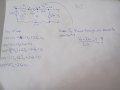
I have 2 unknowns, so I would need 2 equations. But when doing a KVL I get stuck at the Va, do I just do the entire loop?
12V+Vx-4Vx+Vr+2Va = 0
Vr is the voltage drop across the 2ohm resistor.
But now I have 3 unknowns lol. I know the current is the same inside the entire loop since everything is in series.
How do you approach this?
 

WBahn

Joined Mar 31, 2012
32,702
It's not enough to just say that Vr is the voltage drop across the 2 Ω resistor because voltage have polarity. Best is to annotate the diagram with Vr and a polarity indicator, just like Vx is shown.

You've noted that all components have the same current in them, so leverage that. Define the current (again, annotate the diagram and include the polarity of your assumed current) around the circuit as Io. Now write Vx and Va in terms of the independent sources and Io. That will give you one equation with Io as the unknown. Solve for that, the work everything else out.
 

Thread Starter

feryuu

Joined Aug 29, 2025
15
It's not enough to just say that Vr is the voltage drop across the 2 Ω resistor because voltage have polarity. Best is to annotate the diagram with Vr and a polarity indicator, just like Vx is shown.

You've noted that all components have the same current in them, so leverage that. Define the current (again, annotate the diagram and include the polarity of your assumed current) around the circuit as Io. Now write Vx and Va in terms of the independent sources and Io. That will give you one equation with Io as the unknown. Solve for that, the work everything else out.
Ahh I think I got it: Assuming a voltage drop across a resistor is positive: full loop KVL:
-12+Vx-4Vx+Vr+2Va = 0
Subbing in V = I*R:
-12+4I-4(4I)+2(I)+2Va = 0
Solve for I
I = 0.2Va-1.2
Doing a closed loop KVL to include Va,2ohm resistor, and 2Va:
-Va+2Vr+2Va = 0
Subbing in V = I*R
-Va+2I+2Va = 0
Subbing in I: gives Va = 1.71V
Plugging Va into I = -0.858A
If I plug (I) and (Va) into original equation:
-12+4I-4(4I)+2(I)+2Va = 0
I do get 0, so this seems to be correct.....
 

WBahn

Joined Mar 31, 2012
32,702
Ahh I think I got it: Assuming a voltage drop across a resistor is positive: full loop KVL:
-12+Vx-4Vx+Vr+2Va = 0
Subbing in V = I*R:
-12+4I-4(4I)+2(I)+2Va = 0
Solve for I
I = 0.2Va-1.2
Doing a closed loop KVL to include Va,2ohm resistor, and 2Va:
-Va+2Vr+2Va = 0
Subbing in V = I*R
-Va+2I+2Va = 0
Subbing in I: gives Va = 1.71V
Plugging Va into I = -0.858A
If I plug (I) and (Va) into original equation:
-12+4I-4(4I)+2(I)+2Va = 0
I do get 0, so this seems to be correct.....
The problem asked you to find Vo.

You have a sign error in there somewhere.

Just plugging your results into your original equation is NOT a good check -- if you didn't set up the equation correctly, all you are doing is showing that you correctly solved a different problem.

One of the beautiful things about most engineering situations is that the correctness of a proposed solution can be determined from the problem itself.

It's hard to follow your work because you aren't defining I and Vr unambiguously.

Just saying that the voltage drop across a resistor is positive says nothing unless you have defined the polarity of the voltage drop across the resistor. This is an arbitrary assignment, so you must specify it.

Similarly, you must define the reference direction for I.

But since you give a value for Va of 1.71 V, we can use that to verify if it is correct or not.
1768477064364.png


Let's define the bottom node, labeled 'G', as 0 V.

That makes the node C = 1.71 V

Node D is twice this, or 3.42 V.

The makes the voltage across the 2 Ω resistor 1.71 V so as to drive current right-to-left at 855 mA.

This same current flows through the 4 Ω resistor dropping 3.42 V. Because the direction of the current and the definition of Vx, this means that Vx = -3.42 V.

Node A is at -12 V and Node B is 3.42 V higher, or -8.58 V.

This makes the voltage across the dependent source between Nodes B and C equal to (1.71 V - -8.58 V) = 10.29 V

Since this voltage is 4·Vx, the requires Vx to be 10.29 V / 4 = 2.57 V, and not the -3.42 V that it is based on the current flowing through it.

So the answer is incorrect.

So go back and be more careful, starting with an annotated diagram with the definitions of additional variables you introduce. This is not that hard to do and it will save you a lot of grief. It also let's the person reviewing the work, such as a grader or a supervisor, immediately see what you are doing and whether or not you are bring consistent with your definitions.

1768477194876.png

It can also be handy to label the nodes, like I did above so that you can refer to them easily, and declare a common reference node (i.e., 'ground') even if you don't end up needing it.

I also strongly recommend breaking the work into two parts. In the first part, you apply the electrical engineering principles to develop the equations you need, doing as little math as possible. Then draw a line and proceed to solve the equations below the line. Above the line is all EE and below the line is all math. Keep them separate. After you draw the line. Stop and verify that each equation above the line is correct. Go through it term by term and satisfy yourself that there are no silly errors, such as a missing or extra minus sign. Be deliberate about this, since any errors that make it past this point can't be caught easily since you are merely solving a different problem than the one you thought you were solving. So make these equations reflect the EE concepts as transparently as possible. Don't simplify them -- that's math and that belongs below the line.
 

Thread Starter

feryuu

Joined Aug 29, 2025
15
The problem asked you to find Vo.

You have a sign error in there somewhere.

Just plugging your results into your original equation is NOT a good check -- if you didn't set up the equation correctly, all you are doing is showing that you correctly solved a different problem.

One of the beautiful things about most engineering situations is that the correctness of a proposed solution can be determined from the problem itself.

It's hard to follow your work because you aren't defining I and Vr unambiguously.

Just saying that the voltage drop across a resistor is positive says nothing unless you have defined the polarity of the voltage drop across the resistor. This is an arbitrary assignment, so you must specify it.

Similarly, you must define the reference direction for I.

But since you give a value for Va of 1.71 V, we can use that to verify if it is correct or not.
View attachment 362089


Let's define the bottom node, labeled 'G', as 0 V.

That makes the node C = 1.71 V

Node D is twice this, or 3.42 V.

The makes the voltage across the 2 Ω resistor 1.71 V so as to drive current right-to-left at 855 mA.

This same current flows through the 4 Ω resistor dropping 3.42 V. Because the direction of the current and the definition of Vx, this means that Vx = -3.42 V.

Node A is at -12 V and Node B is 3.42 V higher, or -8.58 V.

This makes the voltage across the dependent source between Nodes B and C equal to (1.71 V - -8.58 V) = 10.29 V

Since this voltage is 4·Vx, the requires Vx to be 10.29 V / 4 = 2.57 V, and not the -3.42 V that it is based on the current flowing through it.

So the answer is incorrect.

So go back and be more careful, starting with an annotated diagram with the definitions of additional variables you introduce. This is not that hard to do and it will save you a lot of grief. It also let's the person reviewing the work, such as a grader or a supervisor, immediately see what you are doing and whether or not you are bring consistent with your definitions.

View attachment 362090

It can also be handy to label the nodes, like I did above so that you can refer to them easily, and declare a common reference node (i.e., 'ground') even if you don't end up needing it.

I also strongly recommend breaking the work into two parts. In the first part, you apply the electrical engineering principles to develop the equations you need, doing as little math as possible. Then draw a line and proceed to solve the equations below the line. Above the line is all EE and below the line is all math. Keep them separate. After you draw the line. Stop and verify that each equation above the line is correct. Go through it term by term and satisfy yourself that there are no silly errors, such as a missing or extra minus sign. Be deliberate about this, since any errors that make it past this point can't be caught easily since you are merely solving a different problem than the one you thought you were solving. So make these equations reflect the EE concepts as transparently as possible. Don't simplify them -- that's math and that belongs below the line.
You are correct, I had a wrong sign.
Below I attached a photo of annotated circuit: my stylus for my tablet was acting up.
But before I go any further does this look like the correct approach and if my question is correct? Because if it is, couldnt I just sub in
Io = (Va-2Va/2) into equation below, since Io is the same in entire circuit?
12V-10Io+2Va = 0 ?Bc im abit lost on how to write Va in terms of Io. or vice versa.
 

Attachments

Last edited:

WBahn

Joined Mar 31, 2012
32,702
Io = (Va-2Va/2) into equation below, since Io is the same in entire circuit?
You have the right idea, but as you've expressed it Io is identically zero. Don't forget order of operations. You've made a very common mistake that bites people all the time, especially when they convert a written fraction into a text expression to use in a program or a spread sheet. You need to get in the habit of reviewing equations to see what you wrote is actually what you meant. Also, you need to start tracking your units through your work. Units are perhaps the single most effective error detection tool available to the engineer, because most (not all) mistakes we make (and we are always making them, since we are human) will mess up the units. As it would have here, since you would have ended up with a current on the left being equal to the difference of a voltage and a current on the right.

\(
I_0 \; = \; \frac{V_a \; - \; 2V_a}{2 \; \Omega} \\
I_0 \; = \; - \frac{V_a}{2 \; \Omega}
\)
 

MrAl

Joined Jun 17, 2014
13,667
You are correct, I had a wrong sign.
Below I attached a photo of annotated circuit: my stylus for my tablet was acting up.
But before I go any further does this look like the correct approach and if my question is correct? Because if it is, couldnt I just sub in
Io = (Va-2Va/2) into equation below, since Io is the same in entire circuit?
12V-10Io+2Va = 0 ?Bc im abit lost on how to write Va in terms of Io. or vice versa.
Hello there,

If we label the nodes across the top from left to right: v1, v2, v3, v4 then the following nodal equations result:
v1=-E1
v3-v2=4*(v1-v2)
-v4/R2+v3/R2+v2/R1-v1/R1=0
v4=2*v3

It helps to have this second method to solve the network so you can check your answers from the first method.
Note the 3rd equation above is just the fact that the two currents in the 4 Ohm and 2 Ohm resistors must be equal, so the difference is zero.

You can also calculate Vx and VA from those.
 

Thread Starter

feryuu

Joined Aug 29, 2025
15
You have the right idea, but as you've expressed it Io is identically zero. Don't forget order of operations. You've made a very common mistake that bites people all the time, especially when they convert a written fraction into a text expression to use in a program or a spread sheet. You need to get in the habit of reviewing equations to see what you wrote is actually what you meant. Also, you need to start tracking your units through your work. Units are perhaps the single most effective error detection tool available to the engineer, because most (not all) mistakes we make (and we are always making them, since we are human) will mess up the units. As it would have here, since you would have ended up with a current on the left being equal to the difference of a voltage and a current on the right.

\(
I_0 \; = \; \frac{V_a \; - \; 2V_a}{2 \; \Omega} \\
I_0 \; = \; - \frac{V_a}{2 \; \Omega}
\)
Nice to know I was on right track, was starting to lose my mind lol. Got an A in Calc 3 and Diff Eq. and I sometimes feel I should be wearing a spitbib and a hardhat when looking at a circuit.
But abit of confusion regarding your answer. Im guessing you mean I shouldve wrote it is Io = ((Va-2Va)/2) ,instead of Io = (Va-2Va/2) .
But After subbing this in I get Va = -1.71V & Io = 0.855A, and checking all the other nodes seems to be correct, so Vo = 2Va = -3.42V
 

Thread Starter

feryuu

Joined Aug 29, 2025
15
Hello there,

If we label the nodes across the top from left to right: v1, v2, v3, v4 then the following nodal equations result:
v1=-E1
v3-v2=4*(v1-v2)
-v4/R2+v3/R2+v2/R1-v1/R1=0
v4=2*v3

It helps to have this second method to solve the network so you can check your answers from the first method.
Note the 3rd equation above is just the fact that the two currents in the 4 Ohm and 2 Ohm resistors must be equal, so the difference is zero.

You can also calculate Vx and VA from those.
Ahh I like this, I just checked first method with this one and got all the same answers, thank you. And when determining the voltage drop across R2 we just have to be consistent with the current direction we assumed it to be in the beginning.
 

MrAl

Joined Jun 17, 2014
13,667
Ahh I like this, I just checked first method with this one and got all the same answers, thank you. And when determining the voltage drop across R2 we just have to be consistent with the current direction we assumed it to be in the beginning.
Hi,

Yes it's always good to have a second way to calculate this. You don't have to use Nodal that's just my choice. Whatever you feel more comfortable with.
 
Top