Kitchen timer to drive a relay

Thread Starter

Suzukiman

Joined May 1, 2010
94
I have not abandoned the project yet! Unfortunately some other priorities came up.
I just wish I had thought of using a bread board before, it would have saved me a lot of headaches!

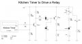
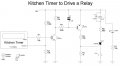
I managed to get the circuit working today and the timer now latches the SCR which lights up a LED. Hopefully I will get some time during the week to test it with a relay. Then I will post the circuit in case someone else is interested.

The beauty of using a LCD timer is the ease of use and the highly visible countdown/countup display at no real cost.

I have managed to get a kitchen timer that can countdown from 24 hours in minutes, as well as one that shows seconds as well, but can only do 1 hour, 59 minutes and 59 seconds.

Watch this space!
 

Kermit2

Joined Feb 5, 2010
4,159
you could use a relay with an extra set of contacts -DPDT - and wire one set of contacts to send power to the coil, in essence making it a latching relay. It would hold as long as power was applied after that, meaning you would have to turn things off before it 'unlatched'
 

Thread Starter

Suzukiman

Joined May 1, 2010
94
you could use a relay with an extra set of contacts -DPDT - and wire one set of contacts to send power to the coil, in essence making it a latching relay. It would hold as long as power was applied after that, meaning you would have to turn things off before it 'unlatched'
Thanks, but I do not have too many contacts on the relays available to me unfortunately, but will keep in mind if the SCR approach is not used.
In actual fact I would prefer to get rid of the relay if possible, but that can only be looked at once I have the first circuit working.
Thanks again.
 

Thread Starter

Suzukiman

Joined May 1, 2010
94
Finally I have a working circuit although I may have broken some electronic rules and have some components working outside their ranges!
Thanks to each one of you that helped with advice, it really helped me on the way and is much appreciated.

Below is the schematic and I will appreciate any suggestions for improvements or value changes. If anyone has the time and inclination a run on a simulator would be great. I do not have an oscilloscope to do proper testing and my electronic skills are lacking at best.

The input is from a small digital kitchen timer that runs on one penlight battery and gives output pulses of about 0.9V-1.5V to a small piezo buzzer.
The SCR latches the relay when a pulse is received.

Again thanks a lot.:)
 

Attachments

Last edited:

Thread Starter

Suzukiman

Joined May 1, 2010
94
Happy it works! I don't think you need C1 or C2....otherwise it looks like it should do the job.

Ken
I had trouble with it switching on randomly when I switched my soldering iron off. The 30 V supply comes from a transformer supply. Possibly some transients and C1, C2 seemed to solve this.
 

KMoffett

Joined Dec 19, 2007
2,918
Try eliminating C1, and connecting C2 to +30V instead of ground. If the noise is coming through the 30V supply, you may want to add a 0.1uF and a 100uF between the supply +/- lines, as close as possible to your circuit.

Ken
 

hobby16

Joined Aug 30, 2010
30
Ken, thanks for the suggestion. I have done that and it works well.
Much better, since your previous C2 connexion didn't make any sense at all.

I don't know why you don't use Potato's schematics which is perfectly sane (the way he connects NPN & PNP gives a SCR already, no need to add one !). I would remove his R2 and D1 and replace R1 by a 100n capacitor and it MUST work.
His C1 & R6 network is equally very well designed (high initial inrush current to move the relay then lower maintaining current), you can replace it with a 100 ohm if you need to lower the component count.
To reset (disconnect the relay), all you need is a push button betwen 0V and the NPN transistor base.
 

Thread Starter

Suzukiman

Joined May 1, 2010
94
I don't know why you don't use Potato's schematics which is perfectly sane (the way he connects NPN & PNP gives a SCR already, no need to add one !).
I will set it up and test soon. I am also looking at a very low current draw to allow battery working. At the moment the schematic I have draws 11.5mA continuously with relay operated, that includes the led. If latching the relay with 2 transistors can reduce this I will be very happy!

Thanks for the suggestions, I will leave feedback on the next test.
 

KMoffett

Joined Dec 19, 2007
2,918
I assume that you're using R8 to drop the difference between the 30V supply and the 24V for the relay. The current drawn by the relay/R8 is ~8.8mA and the LED/R7 draws ~2.8mA. That's ~11.6mA. So, almost all the current is due the the relay and the LED, not the rest of the circuit.

I don't recall...what you want to switch with the relay in the final project. ???

Ken
 

Thread Starter

Suzukiman

Joined May 1, 2010
94
I assume that you're using R8 to drop the difference between the 30V supply and the 24V for the relay. The current drawn by the relay/R8 is ~8.8mA and the LED/R7 draws ~2.8mA. That's ~11.6mA. So, almost all the current is due the the relay and the LED, not the rest of the circuit.

I don't recall...what you want to switch with the relay in the final project. ???

Ken
Ken,
That is correct. The rest of the driver circuit only draws very low current for the duration of the pulse. That stray C2 capacitor was my crude experiment to decouple the base of the T2 transistor. Any circuit keeping the transistors switched on permanantly may draw more current I think. In actual fact the 24V relay I am using now has a coil resistance of 2710 ohms and I think I could maybe even bring the current down slightly.

I need to switch a circuit that requires 30V at about 2 to 4 mA and that made me opt to use the same 30V to drive the relay driver instead of say 9V.

I now nead to build a 9V to 30V step up that could use either a 9V battery or a 9V DC mains PSU as needed with about 50 to 100mA capacity as my present internal transformer PSU is just too bulky.
 

KMoffett

Joined Dec 19, 2007
2,918
Does the switched circuit (30V/2-4mA) need to be isolated from the timer circuit? Could you explain and post a schematic of what your final project is to look like?

Ken
 

Thread Starter

Suzukiman

Joined May 1, 2010
94
Does the switched circuit (30V/2-4mA) need to be isolated from the timer circuit? Could you explain and post a schematic of what your final project is to look like?Ken
Ken,
The 30V does not have to be isolated and can be from the same rail as long as it can be switched on with the timer. In fact the rest of the circuit would be similar to a led between ground to the 30V and with a resistor in series with the 30V. The output could be open or closed at times, thus the latching should not be dependant on the load drawing current.
I was thinking of now dumping the relay (only for this project) and fitting a linear transistor which is latched by the timer pulse.
Maybe you have some ideas on that.
 

Thread Starter

Suzukiman

Joined May 1, 2010
94
OK, tested Potato's diagram, but cannot get it to trigger. I have now added the suggestion to use the cap accross the relay and so reduce the holding current. I now measure 7.0mA drawn totally while the relay is operated and 0.3mA while waiting for the pulses! The random triggering problem seems to be gone and it seems to be functioning as required.
Here is what I have on the breadboard at the moment:


Attachments

Thread Starter

Suzukiman

Joined May 1, 2010
94
Yes, you are right. Ken thanks for your interest and help.
I need to start looking at a better 30V supply and think I will do that in a new thread if you are interested.
Thanks again.
 

KMoffett

Joined Dec 19, 2007
2,918
If you do, please explain what you're trying to accomplish...the big picture. Explain what's wrong with your current 30VDC power supply. And, post a link to this thread as part of you details.

Ken
 

lyonsie

Joined Jan 13, 2013
7
i have just been reading through this thread and was wondering would it be possible to change the circuit to operate on a 5v to 9v power supply. would this simply involve replacing the transistors and relay to suitable components?? thanks
 
Top