The first step is to show YOUR best effort to solve YOUR problems. Then we can see what you are doing right and where you are having problems and offer hints and suggestions to lead you back onto the right path.
Hi WBahn
You will have to bear with me I have 1 assignment on Ac Dc theory to do on a self study course. So this is all new to me does my labelling of diagram look ok so far ? im struggling the next move from here for the resultant current in R2.
The sum of the currents entering a node = the sum of the currents leaving.
This is true for every node in the circuit.
So you will obtain an equation connecting currents for each and every node.
How many equations will that yield in this case?
Note also that KCL has no voltages in it.
KVL = Kirchoff's Voltage Law
The sum of the EMF voltages around any closed loop = The sum of the IR voltage drops in that loop.
You can obtain an equation for each and every loop in the circuit
Note that KVL conains both voltages and currents
How many equations are therefore in your circuit?
These are the basic forms of Kirchoff's laws.
Others here will cut corners and combine these with other ideas to form what are known as the mesh equations which also contain both voltage and current.
These are short cuts that are best studied once the long slog method is fully understood.
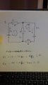
Here is a start on your circuit.
I have labelled the nodes A and B and shown the currents for Node A
The sum of the currents entering a node = the sum of the currents leaving.
This is true for every node in the circuit.
So you will obtain an equation connecting currents for each and every node.
How many equations will that yield in this case?
Note also that KCL has no voltages in it.
KVL = Kirchoff's Voltage Law
The sum of the EMF voltages around any closed loop = The sum of the IR voltage drops in that loop.
You can obtain an equation for each and every loop in the circuit
Note that KVL conains both voltages and currents
How many equations are therefore in your circuit?
These are the basic forms of Kirchoff's laws.
Others here will cut corners and combine these with other ideas to form what are known as the mesh equations which also contain both voltage and current.
These are short cuts that are best studied once the long slog method is fully understood.
Here is a start on your circuit.
I have labelled the nodes A and B and shown the currents for Node A
I am working through this in excruciating detail with you because I think you teaching material is too condensed and that you have either not seen or the basics.
Don't worry once you have done it once you should not need to do it again in such detail and will be able to see how to condense the statements.
The quote above suggests you do not properly understand what a node or loop is, which is part of the trouble.
I have added nodeB to my diagram and three more currents for the three more branches.
It is very very very important to realise that the arrows represent a guess for the directions of the currents.
If the guess is wrong the current will simply come out negative.
We can discuss this as we go along and develop the diagram.
I see you used the word 'junction'.
This implies a connection to me at any rate.
A connection is really a single point in the circuit.
There may be many connections or junctions at a node.
A node is a region of a circuit that is all at the same potential (voltage).
It is not usually a single point but spread out.
I have outlined the boundary of the B node in the circuit with a dashed line.
Can you do this for the A node?
Talking of junctions,
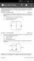
When two wires cross in a drawing we have to indicate if there is a connection or not., as is fig1.
The oldfashioned way is show them definitely not connecting as in fig2
A more modern way is to show them definitely connecting as in fig3
This causes difficulty in some more complicated circuits and the correct implementation of this convention is in fig 4 where any connection has a maximum of three branches, so we can always identify the different branch currents.
The way i see it as 17v goes into R1 as a + current then goes down to R2 am i correct in thinking that the current goes into a resistore as a + current and out a - current ?
The way i see it as 17v goes into R1 as a + current then goes down to R2 am i correct in thinking that the current goes into a resistore as a + current and out a - current ?
I didn't post any values, just some equations connecting three (six) currents ?
It is not a good idea to be too specific about your private details in open forum.
In particular you should never post your own Email here (as some do).
This forum boasts a PM - private messaging service you are advised to use that.
I also suggest you remove your Stanley Baker details.
My company, Studio T is based in Taunton.
 Facebook
 Google
 GitHub
 Linkedin
 590.8 KB Views: 63