Kirchoffs Theory

studiot

Joined Nov 9, 2007
4,998
In order to make progress I will press on, we can come back to make sure you understand what a node is.

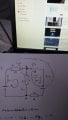
KCL for the node A introduces the equation
\({I_1} = {I_2} + {I_3}\)

We can also write a KCL equation for node B

\({I_4} = {I_5} + {I_6}\)

But this does not introduce any new information since these are really just the branch currents at the other end of each branch.

So there are three unknowns and just one equation.
So the system cannot be solved by KCL alone.

This also brings up the points the if there are N nodes then there are (N-1) independent KCL simultaneous equations.

I have used LaTex to show the equations this time because it occurred to me that you may have thought the rubbishy capital 'I ' used by this forum was a one and hence thought I was entering values into the equations.
Using a proper Roman I will avoid this confusion.

You were also asked to identify the loops on your diagram.

I have done this in the next stage.

Again this is important because this also identifies a direction.
We need two more equations to solve the system and can get these from KVL with all these preliminaries in place.
nodeA2.jpg
 
Last edited:

Thread Starter

John54321

Joined Apr 1, 2015
39
Yes i will go round tomorrow and have a look. There's a lot of history in the village.

I did get the 2 inside loops correct and I knew that another goes around the outside. They were on my initial diagram.

Going from node A in a clockwise motion for loop 1 and 2 i have the following:-

LOOP1: -6 I3 + 17 - 35 I1 = 0

LOOP 2: 34 -4I2 - 6I3 = 0

LOOP 1 : -6(I1 +I2) + 17 - 35I1

-41I1 - 6I2 = - 17

LOOP 2: 34 - 4 I2 - 6 (I1 + I2) =0

-10I2 - 6I1 = -34

Beacause there are 3 branch's I1, I2,I3 i don't get as confussed as having 6 is this ok ?
 

Attachments

Last edited:

studiot

Joined Nov 9, 2007
4,998
Yup you got the node idea firmly planted.

:)

Your question said

Draw the diagram of the following circuit indicating any loops, current directions etc that you need and use Kirchoff's voltage and current laws to calculate the following:..........................

You need to get into good habits so that other people (those marking your work or you yourself in 6 months or 6 years) will be able to understand what you are talking about.
If WBahn gets on your tail he will also bang on about stating the units.

You put down some of it but far from all.

To continue, and please, let us use the three current s I1, I2 and I3 in the directions I have shown.

I will take loop 2 and write down Kirchoff's voltage law.

Sum of the EMFs = +34volts

Sum of the IR drops = (-6I3) + (-4I2)

So +34 = (-6I3) + (-4I2)

Can you now write the KVL equation for loop1?

Using these I made I1 = 1 amp, I2 = -4 amps and I3 = -3 amps

This can be checked by writing the KVL equation for loop3 and substituting these values.
 
Last edited:

studiot

Joined Nov 9, 2007
4,998
I thought you'd ask. That was why I did the more difficult loop.

Look carefully at the diagram.

I have marked a clockwise direction as positive.

Proceeding in a clockwise direction around the loop from the battery positive to the battery negative we go clockwise i.e. in a positive direction.

So the sum of the EMFs is +(the battery voltage)

As we travel round the loop we encounter I3 going the other way through R2 so the voltage drop is negative and equal to -I3 x R2 = -6I3.
Similarly the direction I chose for I2 is against the loop direction so is negative so the voltage drop across R3 is -I2 x R3 = -4I2

So the sum of the IR drops is (-6I3-4I2)

Now how about loop1?
 

Thread Starter

John54321

Joined Apr 1, 2015
39
Loop 1 has been written as the way your arrows point clockwise starting at node A.

I'm off to sleep, thanks for your help I'm slowly getting there and enjoying it.
 

studiot

Joined Nov 9, 2007
4,998
EMF is the 'electromotive force'.

Basically it stands for all the sources of energy input to a circuit or loop, such as batteries, dynamos etc.

The IR drops are basically all the components that dissipate energy

So KVL is essentially an electrical version of the law of conservation of energy

Energy input (EMF) = Energy output (heat via IR drops)

Similarly KCL is the law of conservation of electric charge.

Sleep?
You have three equations and three unknowns
What is stopping you solving them?

For practice try checking your results by working round loop 3 using the currents you have calculated.

Do you understand why some of the currents are negative?

;)
 

Thread Starter

John54321

Joined Apr 1, 2015
39
Yes I think im right in thinking that from a -v to a +v = the emf of the battery. The other way + to a - it's negative potential.

When you cross a resistor in a + direction against the current it changes to - and vice versa.

17v = 35 I1 + 6I3 or should this be
-17v = 35I1+ 6I3 because the r values are +

Sum of IR ( 35I1 + 6I3)
 
Last edited:

studiot

Joined Nov 9, 2007
4,998
What happens if you try both of these (one at a time) in your solution?

You are using a convention. (Actually three of them)
This is arbitrary and nothing to do with the physics in the wires - This causes much confusion and long threads here.
The important thing is that you are consistent.

Most of the world and pretty well all of industry uses what is known as 'conventional current'
Conventional current is positive in the direction from positive towards negative (in DC circuits)

Perversely this site uses a convention that was academically fashionable in 1990s which makes conventional current negative.
So you should always start by establishing the convention in use.

The second convention is purely geometrical and has nothing to do with electricity.
It is the way you work around the circuit and the assumed arrows on the unknown currents and voltages.

The third convention, which happily is universal, is that voltage increases from negative to positive.

In nearly all the literature the equations are arranged so that conventional current is positive.
To use any other you need to add minus signs at various points in all sorts of equations.

So do you know which 'type' of current your study pack is using?
 

Thread Starter

John54321

Joined Apr 1, 2015
39
The assignment is called
Dc and single phase ac theory

I hope this helps.

I have tried to to put the equations into algebra but struggling on how to cancel one out and the divide to get either I1, I2, I3
 

studiot

Joined Nov 9, 2007
4,998
Somewhere it must show you what convention your study pack states.

Does it say current is positive if it flows from negative to positive or positive to negative?
Perhaps it tells you this when it shows a single battery and a single resistor. That is usual.

This is not the circuit geometrical convention.

We must know this to write the equations correctly.
 

studiot

Joined Nov 9, 2007
4,998
Don't you have a textbook, or are you supposed to guess?

What sort of course is this by the way?

Your original post showed the use of Kirchoff in the first part.
The next part showed Thevenin's Theorem, Norton's Theorem and the Superposition Theorem.
But these are not on this latest sheet, are you covering them?

Kirchoff is the simplest since it is applied directly to the circuit as it stands and you work with the actual currents and voltages appearing at any point in the circuit.
It is also generally applicable, which means it will always work (in the type of circuits you will come across).

The other methods, including the three above, generally require you to redraw the circuit in a special manner, transforming (changing) some parts.

Which all adds up to....Good drawing is essential.

I do not know where you are with maths and simultaneous equations, but we can work through my solution in more detail if you like???
 

Thread Starter

John54321

Joined Apr 1, 2015
39
It's a HNC/D in Aeronautical Engineering. The first part of the course has 6 assignment's to complete. I've done 2 this is the 3rd assignment.

We can carry on and if its wrong I will just get the assignment back to re-work.
 

studiot

Joined Nov 9, 2007
4,998
I have used a combination of two methods to solve these equations
Substitution and adding equations to eliminate a variable.
The three equations are


\({I_1} + {I_2} = {I_3}..........1\) KCL

\(17 = 35{I_1} + 6{I_3}........2\) KVL loop1

\(34 = - 6{I_3} - 4{I_2}..........3\) KVL Loop2
Rearrange 1

\({I_2} = \left( {{I_3} - {I_1}} \right)\)
substitute into 3

\(34 = - 6{I_3} - 4\left( {{I_3} - {I_1}} \right) = - 6{I_3} - 4{I_3} + 4{I_1} = - 10{I_3} + 4{I_1}........4\)
multiply 4 through by 6

\(204 = - 60{I_3} + 24{I_1}....................5\)
multiply 2 through by 10

\(170 = 60{I_3} + 350{I_1}.......................6\)
add 5 and 6

\(374 = 374{I_1}\)

\(374 = 374{I_1}\)

\({I_1} = 1\)

Substitute value into 2

\(17 = 35 + 6{I_3}\)

\(6{I_3} = - 18\)

\({I_3} = - 3\)
Substitute into 1

\(1 + {I_2} = - 3\)

\({I_2} = - 4\)

So now it is time to decide what these values mean and to calculate the other items in the first section of your paper (power etc)

See how you get on with those.
 
Last edited:

studiot

Joined Nov 9, 2007
4,998
Worked for me.

But at HNC/D level you really should be able to solve simple equations like this for yourself.

What about the rest of the question 1?
 

Thread Starter

John54321

Joined Apr 1, 2015
39
I did take a pic of at the cemetery of the guy you mentioned.Col J R M Chard VC RE but this site wouldn't upload it.

Yes all understood for Q1.1 Thanks very much

For question 1.2 do I use loop 1 voltage 17v and ohms law to get the potential dropped over R2 Please ?
 
Top