KiCad 10.0.4 74HC163 simulation

Thread Starter

Dave Lowther

Joined Sep 8, 2016
345
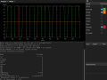
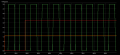
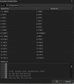
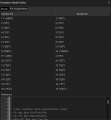
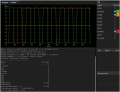
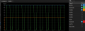
I'm new to using simulators. I thought I'd give KiCad simulation a try as I've been using KiCad for several years. The issue I'm having is that the Q outputs of the 74HC163 start low, as intended, but immediately go to half Vcc, which AI told me was an undefined state, indicating that the model was misbehaving in some way.

I spent most of yesterday reading FAQs, looking for tutorials, and having a dialogue with Google AI mode. The AI seemed promising to start with, but after a few hours it started contradicting itself and many of its suggestions caused simulation errors. The AI was very definite about what was going wrong and what I should do that would fix it. That was until I said I'd had enough of trying 20+ changes none of which got the 74HC163 working and some made it worse, at which point it apologised for guessing and getting me to do trial and error changes :-(

I got the 74HC library from https://github.com/kicad-spice-library/KiCad-Spice-Library/blob/master/Models/Digital Logic/74HC.LIB
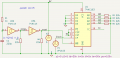
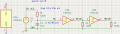
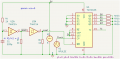
I designed the schematic myself. At one point I had !PE connected to reset, but edited it to be tied up at one point due to AI asking me to try it and see if there was a problem in the model associated with PE, I forgot to revert that. AI also suggested using a pull down between the junctions of pins 3 to 6 and 0V, which didn't fix the problem, so I reverted that.
1784041528764.png

With the help of AI I got the 74HC14 section working. I needed to add the pull downs on the outputs to make it work. So I added the same pull downs on the 74HC163 Q outputs.
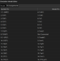
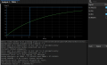
1784041649716.png

1784042270298.png

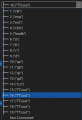
It won't let me set pin 16 to Not Connected.

It would be greatly appreciated if someone could give me some help with getting this working. I.E. getting the 74HC163 Q outputs counting. Or perhaps tell me I'm wasting my time using KiCad for digital simulation and suggest a known working alternative, bearing in mind that I really want to do the schematic and board layout in KiCad, and prefer not to learn another schematic entry tool.

I was in two minds about whether to post here or post in the KiCad forum. I plumped for here because I see frequent posts on this forum from people who seem to be very knowledgeable about LTspice. IDK how similar that is to the ngspice that KiCad uses.
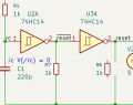
 
You shouldn't need any resistors other than R1, together with C1, both of which could be increased in value to give a longer reset pulse, in case the supply takes longer to stabilise. Everything looks as if it should work in reality, but 1k pulldowns on the outputs of the counter aren't needed. Pin 16 is the supply pin, so must be connected, as must pin 8 to Gnd.
 

Thread Starter

Dave Lowther

Joined Sep 8, 2016
345
Thank you for replying.
You shouldn't need any resistors other than R1
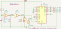
Just to demonstrate what happens without one of the pull downs, I moved R6
1784044510773.png
And then it doesn't plot anything for "reset".
1784044708696.png
I realise the pull downs aren't required in real life. IIRC AI said something like "pull downs are needed to make digital outputs plottable". The 5V (blue line at the top on this screen snip) looks stable from time 0.
The reset signal (in the first simulation output screen shot) should be long enough as there are two rising clock edges whilst reset is low.
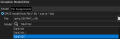
There aren't any options for Vcc or Gnd in the model pin mapping drop down
1784045127038.png

The model text is attached. I've not yet studied the modelling language. I'm attaching it in case it's required for further diagnosis of this problem.
 

Attachments

Thank you for replying.

Just to demonstrate what happens without one of the pull downs, I moved R6
View attachment 369513
And then it doesn't plot anything for "reset".
View attachment 369515
I realise the pull downs aren't required in real life. IIRC AI said something like "pull downs are needed to make digital outputs plottable". The 5V (blue line at the top on this screen snip) looks stable from time 0.
The reset signal (in the first simulation output screen shot) should be long enough as there are two rising clock edges whilst reset is low.
There aren't any options for Vcc or Gnd in the model pin mapping drop down
View attachment 369516

The model text is attached. I've not yet studied the modelling language. I'm attaching it in case it's required for further diagnosis of this problem.
Very strange. Now I know why I never use simulators, only breadboard hardware!
 

Thread Starter

Dave Lowther

Joined Sep 8, 2016
345
are the voltages from Q1, Q2 Q3 also like that? there are only two possibilities, must be a bad model or bug in Sim..
Yes all 4 are the same. The simulator text window in post #1 shows the initial condition for all the Q outputs is 0. They all immediately jump to 1/2 Vcc, which AFAIK means "invalid or unknown state"
I was concerned that there might a 3rd possibility, user ignorance. E.G. I didn't know to start with that I couldn't just simulate a real world schematic with no pull downs.
I think I got the 74HC library from a reputable source. If you happen to know where I can get some other 74HC163 model that's known to work I'll give that a try to eliminate the bad model possibility.
 

Thread Starter

Dave Lowther

Joined Sep 8, 2016
345
I never use simulators, only breadboard hardware!
Me too, until now. I'm helping a relative beginner who wants to simulate a relatively complex (maybe 100 chips) system designed with 74HC. So I thought I'd just simulate a small simple part of it in KiCad to get started. So far it's been a bit of a disappointment, but I'm not giving up yet. That's why I posted here, in the hope of being told what I'm doing wrong, or to be told trying to simulate 74HC with KiCad is a waste of time.
 

Thread Starter

Dave Lowther

Joined Sep 8, 2016
345
output is supposed to track supply... what happens if you change supply voltage to say 3V3?
I just changed .param vcc to 3.3 from 5. I didn't touch the 5V voltage source or the 5V clock. It seems that the simulator ignores the power pins on the 74HC163 because the Q0 output is now at 1/2 of 3.3V.
1784059451091.png


1784059486710.png
 

WBahn

Joined Mar 31, 2012
33,002
There appear to be some KiCAD-specific things in the model file that I'm not familiar with, so there's guessing going on here.

Notice how the original sim result says, "Note: gnd in a subcircuit is not set to 0 automatically" It also says that Pin 8 is disconnected. Those both lead me to wonder whether your subcircuit is being properly referenced to the simulator's ground.

It also seems, based on the names of things in the model, that the model is using TTL levels or specifications, implying that it was thrown together by taking a hatchet to another model.

While it probably doesn't have any impact of the sim, a 1 kΩ resistor is a very heavy load on an HC output. You want to keep the current draw from the outputs about an order of magnitude lower.

As you are discovering, AI tools are very hit and miss. They can be good sources of hints and expose avenues to explore, but the good stuff is generally buried in a bunch of crap. If you already have sufficient proficiency in the topic, you can filter out the good nuggets from the slop, but if you are trying to use it to guide you on something that you don't have much familiarity with, they will tend to very confidently feed you a bunch of meaningless drivel.
 

Thread Starter

Dave Lowther

Joined Sep 8, 2016
345
There appear to be some KiCAD-specific things in the model file that I'm not familiar with, so there's guessing going on here.
Thank you for your reply.

Notice how the original sim result says, "Note: gnd in a subcircuit is not set to 0 automatically" It also says that Pin 8 is disconnected. Those both lead me to wonder whether your subcircuit is being properly referenced to the simulator's ground.
At one point in the trial and error AI guided fault finding I did have the KiCad power symbols for Vcc and Gnd connected to the power rails, but that made no difference. I still got that warning.

This is a simplified version, without the 163, with GND and VCC symbols. There is no power connection to the 7414
1784199566705.png

This simulation is fine, but it still has that warning:

1784199702376.png

AI told me (and it seems to be correct) that the models contain the code to automatically connect the power pins to VCC and GND.

It also seems, based on the names of things in the model, that the model is using TTL levels or specifications, implying that it was thrown together by taking a hatchet to another model.
I'm surprised and disappointed that there seems to be no comprehensive source of tested / maintained / working libraries for any 74xx family for the simulator in KiCad. I guess it's because there's little demand for 74xx these days.

While it probably doesn't have any impact of the sim, a 1 kΩ resistor is a very heavy load on an HC output. You want to keep the current draw from the outputs about an order of magnitude lower.
My 'understanding' is the the digital simulation doesn't measure current. Which is another disappointment. E.G. I assume that means there'd be no indication of exceeding fan out, but perhaps not an issue when driving CMOS inputs. IDK what it would do about capacitive loading. I guess it ignores that too.

As you are discovering, AI tools are very hit and miss. They can be good sources of hints and expose avenues to explore, but the good stuff is generally buried in a bunch of crap. If you already have sufficient proficiency in the topic, you can filter out the good nuggets from the slop, but if you are trying to use it to guide you on something that you don't have much familiarity with, they will tend to very confidently feed you a bunch of meaningless drivel.
I was quite impressed by its ability to accept screen shots of schematics and E.G. tell me that I had a power up reset block. It would have helped if it was a bit more humble to start with, and tell me some kind of confidence level for its suggestions, rather than waiting until I worked out it wasn't helping. It only apologised for guessing and using trial and error when I told it that I was unhappy about the number of attempts it had at "fixing" the problem and at best it's suggestions made no improvements, at worst they broke the simulation.

I'm beginning to think that simulating a large (100 ish) 74xx project is going to be more of a time waster than just prototyping the hardware in real life. Perhaps on a breadboard with a slow enough clock to not have a problem with stray capacitance. Do you know of any simulator that has good support for 74xx?
 
Last edited:

eetech00

Joined Jun 8, 2013
4,711
Thank you for replying.

Just to demonstrate what happens without one of the pull downs, I moved R6
View attachment 369513
And then it doesn't plot anything for "reset".
View attachment 369515
I realise the pull downs aren't required in real life. IIRC AI said something like "pull downs are needed to make digital outputs plottable". The 5V (blue line at the top on this screen snip) looks stable from time 0.
The reset signal (in the first simulation output screen shot) should be long enough as there are two rising clock edges whilst reset is low.
There aren't any options for Vcc or Gnd in the model pin mapping drop down
View attachment 369516

The model text is attached. I've not yet studied the modelling language. I'm attaching it in case it's required for further diagnosis of this problem.
If you are using that model, and the LTspice simulator with Kicad, there will be many problems.
Basically, the model (and the linked 74HC.lib) is not written for LTspice, and is incompatible. It is written for the Intuisoft simulator.
 

Thread Starter

Dave Lowther

Joined Sep 8, 2016
345
If you are using that model, and the LTspice simulator with Kicad, there will be many problems.
Basically, the model (and the linked 74HC.lib) is not written for LTspice, and is incompatible. It is written for the Intuisoft simulator.
IDK enough about simulators to know whether this is a pedantic response, it's not intended to be. KiCad uses ngspice not LTspice.
I believe the simulator used by KiCad is somewhat compatible with models for LTspice. Currently I'm not having any success finding any library for 74HC163 that works. If you happen to know of a good ngspice or even LTspice library for 74HC163, or even some other flavour like HCT or LS I'd like to try it. So far I'm definitely getting the impression that simulation (including learning curve) is going to be more time consuming, and less reliable, than building a prototype.
 

eetech00

Joined Jun 8, 2013
4,711
IDK enough about simulators to know whether this is a pedantic response, it's not intended to be. KiCad uses ngspice not LTspice.
I believe the simulator used by KiCad is somewhat compatible with models for LTspice. Currently I'm not having any success finding any library for 74HC163 that works. If you happen to know of a good ngspice or even LTspice library for 74HC163, or even some other flavour like HCT or LS I'd like to try it. So far I'm definitely getting the impression that simulation (including learning curve) is going to be more time consuming, and less reliable, than building a prototype.
You mentioned LTspice.
You need to be clear on the type of simulator you are using with Kicad. Kicad can use different simulators and they are not all the same. Each has their own spice extensions, and may or may not be compatible with the model your using.
The model you posted is not compatible with LTspice.
 

Thread Starter

Dave Lowther

Joined Sep 8, 2016
345
You mentioned LTspice.
You need to be clear on the type of simulator you are using with Kicad. Kicad can use different simulators and they are not all the same. Each has their own spice extensions, and may or may not be compatible with the model your using.
I'm not sure what I did wrong here. I thought I'd been clear in the opening post.
I see frequent posts on this forum from people who seem to be very knowledgeable about LTspice. IDK how similar that is to the ngspice that KiCad uses.
Sorry if I caused some confusion.
 

Thread Starter

Dave Lowther

Joined Sep 8, 2016
345
Here at the 74HC files that work for me in LTspice.
Thank you for taking the time to post.

The zip files contain the LTspice symbols.
I'm not sure what role they would play in KiCad. It already has the symbols in the schematic editor.

You must add the .lib 74HC_v.lib directive when simulating with them.
IDK if that's necessary in KiCad because it has this method of assigning libraries to symbols, e.g. for the 74HC163 from 74HC_v.lib:
1784211347824.png
It also has this for mapping the model pins to the schematic pins:
1784212362552.png
When I run the simulation I get this final line in the simulator output console:
"Too few parameters for subcircuit type "74hc163" (instance: xxu1)"
Whether or not I include the directive makes no difference
 

Attachments

Top