Facebook
 Google
 GitHub
 Linkedin

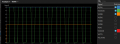
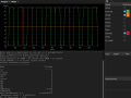
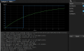
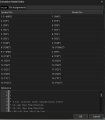
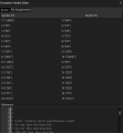
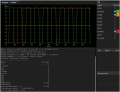
I'm new to using simulators. I thought I'd give KiCad simulation a try as I've been using KiCad for several years. The issue I'm having is that the Q outputs of the 74HC163 start low, as intended, but immediately go to half Vcc, which AI told me was an undefined state, indicating that the model was misbehaving in some way.
I spent most of yesterday reading FAQs, looking for tutorials, and having a dialogue with Google AI mode. The AI seemed promising to start with, but after a few hours it started contradicting itself and many of its suggestions caused simulation errors. The AI was very definite about what was going wrong and what I should do that would fix it. That was until I said I'd had enough of trying 20+ changes none of which got the 74HC163 working and some made it worse, at which point it apologised for guessing and getting me to do trial and error changes :-(
I got the 74HC library from https://github.com/kicad-spice-library/KiCad-Spice-Library/blob/master/Models/Digital Logic/74HC.LIB
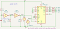
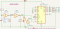
I designed the schematic myself. At one point I had !PE connected to reset, but edited it to be tied up at one point due to AI asking me to try it and see if there was a problem in the model associated with PE, I forgot to revert that. AI also suggested using a pull down between the junctions of pins 3 to 6 and 0V, which didn't fix the problem, so I reverted that.
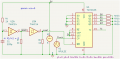
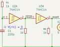
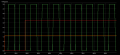
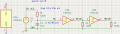
With the help of AI I got the 74HC14 section working. I needed to add the pull downs on the outputs to make it work. So I added the same pull downs on the 74HC163 Q outputs.
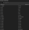
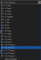
It won't let me set pin 16 to Not Connected.
It would be greatly appreciated if someone could give me some help with getting this working. I.E. getting the 74HC163 Q outputs counting. Or perhaps tell me I'm wasting my time using KiCad for digital simulation and suggest a known working alternative, bearing in mind that I really want to do the schematic and board layout in KiCad, and prefer not to learn another schematic entry tool.
I was in two minds about whether to post here or post in the KiCad forum. I plumped for here because I see frequent posts on this forum from people who seem to be very knowledgeable about LTspice. IDK how similar that is to the ngspice that KiCad uses.
I spent most of yesterday reading FAQs, looking for tutorials, and having a dialogue with Google AI mode. The AI seemed promising to start with, but after a few hours it started contradicting itself and many of its suggestions caused simulation errors. The AI was very definite about what was going wrong and what I should do that would fix it. That was until I said I'd had enough of trying 20+ changes none of which got the 74HC163 working and some made it worse, at which point it apologised for guessing and getting me to do trial and error changes :-(
I got the 74HC library from https://github.com/kicad-spice-library/KiCad-Spice-Library/blob/master/Models/Digital Logic/74HC.LIB
I designed the schematic myself. At one point I had !PE connected to reset, but edited it to be tied up at one point due to AI asking me to try it and see if there was a problem in the model associated with PE, I forgot to revert that. AI also suggested using a pull down between the junctions of pins 3 to 6 and 0V, which didn't fix the problem, so I reverted that.
With the help of AI I got the 74HC14 section working. I needed to add the pull downs on the outputs to make it work. So I added the same pull downs on the 74HC163 Q outputs.
It won't let me set pin 16 to Not Connected.
It would be greatly appreciated if someone could give me some help with getting this working. I.E. getting the 74HC163 Q outputs counting. Or perhaps tell me I'm wasting my time using KiCad for digital simulation and suggest a known working alternative, bearing in mind that I really want to do the schematic and board layout in KiCad, and prefer not to learn another schematic entry tool.
I was in two minds about whether to post here or post in the KiCad forum. I plumped for here because I see frequent posts on this forum from people who seem to be very knowledgeable about LTspice. IDK how similar that is to the ngspice that KiCad uses.