An RC Servo doesn’t just work with a PWM signal. It requires a very specific signal. It must run at 50Hz and the pulse width must be between 1.0 and 2.0 ms. 1.5ms centers the servo. See this Wikipedia article, If you don’t use a servo controller to move your servo, it’s unlikely to work
You can create the required signal with a 555 ICs. Warning, the circuits with one 555 don’t always work with all servos. Search for “555 servo controller” or “555 servo tester”. There are literally hundreds of published circuits. You can also search for “two position servo controller” as this meets your purpose.
You could use model airplane components, but that would be expensive.
You could use a microcontroller such as an Arduino Nano, but unless you are already familiar with Arduinos there is a steep learning curve.
Basically, in order to use a servo, you do need a specific controller. I don’t think (actually I am sure) that your module will work alone. Even if you connect the PWM pins.
An RC Servo doesn’t just work with a PWM signal. It requires a very specific signal. It must run at 50Hz and the pulse width must be between 1.0 and 2.0 ms. 1.5ms centers the servo. See this Wikipedia article, If you don’t use a servo controller to move your servo, it’s unlikely to wo
You can create the required signal with a 555 ICs. Warning, the circuits with one 555 don’t always work with all servos. Search for “555 servo controller” or “555 servo tester”. There are literally hundreds of published circuits. You can also search for “two position servo controller” as this meets your purpose.
You could use model airplane components, but that would be expensive.
You could use a microcontroller such as an Arduino Nano, but unless you are already familiar with Arduinos there is a steep learning curve.
Basically, in order to use a servo, you do need a specific controller. I don’t think (actually I am sure) that your module will work alone. Even if you connect the PWM pins.
Perhaps in attempting to achieve the primary goal, that of triggering a trap door; a servo will work if properly controlled. But thats more involved than a simple solenoid plunger. I was young when I took apart a doorbell. It had two magnetic plungers that would ring the doorbell with either a double chime or a single chime. It could be wired to indicate when someone rang the bell at the front door or at the side door.
I'm thinking something like that could easily pull a trigger and spring the trap. Using a servo seems like a bit overkill. Since it should be becoming clear that a servo is more cumbersome than a simple plunger design, perhaps using something other than the servo would be better suited.
I have a bunch of old lawn sprinkler control valves that operate off of 24VAC. No, that won't serve your purpose, but I have tested them with a 12VDC battery, and yes, they do trigger. While it's not likely you can modify one of these solenoid valves, you could - in theory - use one to trigger a release using a jet of air. That's exactly the idea I have for my control valves, that of using compressed air to launch a paper rocket. The grand children can build their own rockets and with the push of a button, launch a rocket. Other versions they've enjoyed was the "Stomp" rocket launcher. But kids get excited and want to stomp on a 2 liter coke bottle while another is loading the launch pad. Compressed air controlled by an adult with the child and their individual rocket - they can launch their own rocket. So maybe next spring I'll be building something just for that purpose.
Now: Back on topic: A trigger that can be tripped by a puff of air can do the same work a servo or a solenoid plunger could do. You could even construct an air powered solenoid if the trigger takes more effort than just a puff of air.
The point is there are more options. Even using a DC motor with a spring and an arm can be used to trip the trigger. Give me a bit and I'll bang out a drawing to illustrate more clearly what I have in mind.
Simple operation: Power the motor briefly with the polarity shown and the motor will tug against the spring and push down on the trigger plate. Either way, a bird can trigger it or you can remotely trigger it. When the brief energy to the motor cuts off the spring will pull the armature back to some neutral point. It's ready to be remotely triggered again. Fast, quiet, efficient; provided you use an adequately sized motor and a strong enough spring to prevent the motor from spinning 360˚. All you would need is a proper voltage motor and source. Since you're using 5V I'd start by experimenting with small motors out of an old CD player. They draw very little energy and provide a very small push (or pull, however you set it up). If the proposed CD player motor is too small or weak you could likely find a DC Brushed motor in a scrap printer. Gaud knows I have plenty of those laying around as well. With a little more circuitry you could even use a stepper motor; but I wouldn't recommend it. It's more complicated and may require a manual or electronic reset to ready the trap again.
The switch you linked to should easily handle the power needed. And with this arrangement there is no need for a servo, which can be a little noisy.
Hey! This is just a thought. Thinking outside the box. Or the bird cage in this case.
To be honest, I don't know how your trap is triggered, nor do I know how much power is needed to trigger it. Certainly a servo will likely have the needed power since it is often geared down, but that gearing makes it slower and noisier. This solution is purely magnetic energy being put into the rotation of the motor which is inhibited by the spring. I would go even further to suggest you put some kind of stop blocks to prevent the motor from over-rotating.
One reason why I think a servo would not be a suitable solution is because it requires power at all times. To fully extend or retract the servo it needs a PWM signal of either 1mS or 2mS to operate. This would negate the idea of using a key fob (or other intermittent transmitter) to trigger and reset the servo. First, you'd have to (let's assume) extend the servo to spring the trap, then you''d have to retract it to reset it. With the sprung motor (above) you use no power until the desired moment you want to spring the trap. Then when you give the command the motor tries to rotate but is inhibited by the spring and some kind of limiter to spring the trap. As soon as you let go of the button the motor becomes de-energized and the spring returns it to the ready position.
To be clear, more knowledge about the trap and how it works would be helpful. Thus far we seem to be guessing at solutions to the TS's assumed approach. Even if you opt for a spring plunger solenoid to trigger the trap (spring already built in) you only power the circuit when desired. And should you look away and a bird enter the trap at just that moment, there's a chance the bird could spring the trap on their own. A win - win situation as I see it.
Perhaps in attempting to achieve the primary goal, that of triggering a trap door; a servo will work if properly controlled. But thats more involved than a simple solenoid plunger. I was young when I took apart a doorbell. It had two magnetic plungers that would ring the doorbell with either a double chime or a single chime. It could be wired to indicate when someone rang the bell at the front door or at the side door.
I'm thinking something like that could easily pull a trigger and spring the trap. Using a servo seems like a bit overkill. Since it should be becoming clear that a servo is more cumbersome than a simple plunger design, perhaps using something other than the servo would be better suited.
I have a bunch of old lawn sprinkler control valves that operate off of 24VAC. No, that won't serve your purpose, but I have tested them with a 12VDC battery, and yes, they do trigger. While it's not likely you can modify one of these solenoid valves, you could - in theory - use one to trigger a release using a jet of air. That's exactly the idea I have for my control valves, that of using compressed air to launch a paper rocket. The grand children can build their own rockets and with the push of a button, launch a rocket. Other versions they've enjoyed was the "Stomp" rocket launcher. But kids get excited and want to stomp on a 2 liter coke bottle while another is loading the launch pad. Compressed air controlled by an adult with the child and their individual rocket - they can launch their own rocket. So maybe next spring I'll be building something just for that purpose.
Now: Back on topic: A trigger that can be tripped by a puff of air can do the same work a servo or a solenoid plunger could do. You could even construct an air powered solenoid if the trigger takes more effort than just a puff of air.
The point is there are more options. Even using a DC motor with a spring and an arm can be used to trip the trigger. Give me a bit and I'll bang out a drawing to illustrate more clearly what I have in mind.
Hi T,
I agree, that there are many options, I gave one earlier, but that wasn't satisfactory.
I'm guessing that this is a Relay control and the servo is an error.
I had a 70s camera bulb, that had a long tube and could control this, also a fishing wire pull out stick, but I think for cenvenience, this trigger would be best.
C
It appears the red and blue wires are the switched leads. It's hard to tell if the white and black wires are hard wired together. Based on the information it would appear that black and white are common. A simple check for continuity between them should tell for sure if that's the case. The board IS a double sided board (as far as I can tell). So black and white may be common to each other. If that's the case then the red and blue wires are the switched source. Based off the video on the key fob you can program it to work with a single button to activate only during the time you depress the button, or program it to switch ON with the first push then OFF with the second push. OR you can program it to work with a dual button fob (A & B) where A turns it on and B turns it off. In all cases the module was either providing power TO the LED. In that case use of a motor or a spring plunger solenoid would be the easiest approach. Looks pretty straight forward to me. But I tend to think in pictures. I can express more with a picture than I can with thousands of words.
If controlling a higher current is necessary you can use the module to activate a small relay, one that is designed for the voltage and current you plan on using to trigger the trap.
Hi,
I wonder if this could control a solenoid? (I think it's been mentioned?)
If so this would be what I think is the best solution, as it could be used from a hide or similar.
C
Hi everyone, thanks for all chipping in with ideas and potential solutions. Unfortunately I don't really have the time to explore all of the options here. I did connect a solenoid (which I know works) to the unit but nothing happened.
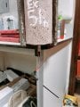
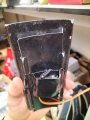
I did a bit more digging around online and decided to go with a more expensive but supremely easier option of a radio controller and servo https://youtube.com/shorts/yT5mHkWAcBU?feature=share see here. The trap is inside the nestbox on the desk above the green box on the floor. The click sound you can hear is the trap shutting. There are some photos of the early prototype. I'll need to mount the servo onto the trap properly, protect the wiring from the elements and wear and tear. And also figure out a wat to hide the receiver (birds are wary of new things showing up around their nest box). Once again though thanks for all the comments. You're all extremely patient!
Hi everyone, thanks for all chipping in with ideas and potential solutions. Unfortunately I don't really have the time to explore all of the options here. I did connect a solenoid (which I know works) to the unit but nothing happened.
I did a bit more digging around online and decided to go with a more expensive but supremely easier option of a radio controller and servo https://youtube.com/shorts/yT5mHkWAcBU?feature=share see here. The trap is inside the nestbox on the desk above the green box on the floor. The click sound you can hear is the trap shutting. There are some photos of the early prototype. I'll need to mount the servo onto the trap properly, protect the wiring from the elements and wear and tear. And also figure out a wat to hide the receiver (birds are wary of new things showing up around their nest box). Once again though thanks for all the comments. You're all extremely patient!
Hi McM,
I'm glad that you're on the way to success.
Before you throw the trigger away, perhaps you could try looking at the original Aliexpress advert again, scroll to the bottom, and follow the set-up proceure, then if no good, throw it in the 'to look at later' drawer.
C
 Facebook
 Google
 GitHub
 Linkedin