It can do 0 to 100% or here tweaked R's for <1% to > 99% PWM.
The Feedback fixed R may be a 100k or more pot depending on required range of freq. scaled by C.
Vcc can be anything up to the limit but adjust pullup for current limit and speed response.
The adjustments are independent and the design is the same ,but input bias currents may be a problem on yours or choice of pot values.
I think it is difficult to achieve with the 555 to vary the frequency and for the duty cycle to remain fixed. Do you know any colleagues with a design without programming that can do it?
It can do 0 to 100% or here tweaked R's for <1% to > 99% PWM.
The Feedback fixed R may be a 100k or more pot depending on required range of freq. scaled by C.
Vcc can be anything up to the limit but adjust pullup for current limit and speed response.
The adjustments are independent and the design is the same ,but input bias currents may be a problem on yours or choice of pot values.
Maybe they don't understand me. In this circuit after the useful cycle is set, for example at 5% at 10 Hz; Leaving the useful cycle potentiometer untouched, by varying the frequency, for example to 200 Hz, the useful cycle will vary, and it is desired that it remain at 5%.
The design in #23 uses one LM339/LM393 to allow adjustment from 0% to 100% duty-cycle with no change in frequency.
The duty-cycle can be adjusted by a pot or a control voltage.
That's about as simple as it can get.
circuits in posts 4, 11, 15, 20, 22, 23, all show valid solutions.
the idea is to generate non-square signal... (even sine will do but adjusting duty cycle will not be linear - so it is better to stick with sawtooth or triangular since they have linear slopes).
circuit in post 15 has 555 oscillator that has square wave output but in this case voltage across capacitor is taken since it has desired shape. with R1 you can change frequency. voltage peaks across capacitor C1 will still be the same - and that is what we want. note that this voltage does not go fully from 0 to Vcc. it is only about 1/3 of that... which is why R5 had to be padded by equal values fixed resistors R4 and R6. With R5 one can select voltage between 1/3 and 2/3 of Vcc. this voltage controls duty cycle of the PWM output.
a) 555 produces low frequency signal.
b) matching PWM output. when Vc1 is higher than Vr5 output of PWM output is reset. when it is lower, it is set. to change this just swap the comparator inputs.
c) same as "a" but frequency is higher. duty cycle here is determined by R5 and in this example is about 33%
d) same as "b" but frequency is higher and since Vr5 was not changed, duty cycle is still the same (about 33%), even though frequency is higher.
Thank you so much. Taking into account your suggestions, I will simulate the circuits to see in the range of 10 to 250 Hz how much the useful cycle varies (1 to 15% is the range that I will work), since it should be as invariable as possible. What do you think if you place a current source to charge the capacitor and achieve triangular wave, it will be better to achieve immobility of the useful cycle?
The frequency variation from 10 to 250 Hz would best be done with an audio Log pot to make the tuning easier at the max range and quicker at the low f. Freq. is inversely proportion to R.
Tune the cap to the range you need around 100 nF and 0.7 Meg ... or 470 nF and 150 k
for near 10 Hz.
Limiting the % PWM range come down to choosing the correct fixed R values on either side of the pot. as mine does 0 to 100% with 3 equal values.
There are other ways to make triangle waves but with no clear advantage.
You problem was you were late in defining your limits.
Greetings. I haven't been able to do tests. I am very grateful. I want to simulate this idea in the frequency range 10-250 Hz to see how much the variation is, I think it should not vary more than 0.1%.
I entered the forum searching on Google for a circuit that would not vary the useful cycle when the frequency varied and I found an appropriate topic in this forum, but not being able to see the links I created a topic with the same name. The explanation is a bit long but I must explain why the idea came to me.
.
You have already been provided with several working versions of what You have "apparently" been asking for.
Separate, independent control of- PWM-Frequency, and PWM-%.
Maybe there are Language difficulties going on ?????
Your language translation of "% of PWM" comes to us English speakers as "Useful-Cycle".
"Useful-Cycle" does not have a proper Electronics-definition in English,
so everyone speaking English just assumed that it meant %-PWM.
Maybe You are referring to something else ?
If You could provide more information as to what You are trying to accomplish with your Project,
maybe it would become better understood by us English speakers.
.
.
.
That is a very small error band. To achieve that you will need opamps or comparators with very low input offset voltage errors and input bias currents, and very low temperature coefficients of both. Also, a timing capacitor with very low dissipation, and high precision resistors. Finally, since we know nothing about the ambient environment where the circuit will be operating, try to match the temperature coefficients of R4, R5, and R6 (schematic #33).
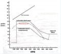
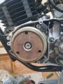
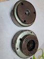
Good morning friends. As I explained before, I entered the forum looking for a circuit because of an idea. This is an electronic signal simulator of an inductive motorcycle sensor. Below I publish photos.
This signal is composed of a period (corresponding to one turn of the crankshaft) in which there is a positive and a negative pulse with a separation that will depend on the length of the arc of the protruding blade of the flywheel. The objective is to verify in the bank, cdi and tci (both acronyms correspond to ignition switches) with this type of input signal; but not only that it works, but also verify its response curve and its variations when varying the length of the arc or reluctor on the steering wheel. Then many ideas arose, such as extracting the signal from a computer through some type of tool, such as labview (the best but least practical for me), using counters, two monostables, an astable governing a monostable; But I also thought that if I could achieve an astable that the duty cycle remained stable when varying the frequency, it would be the most effective and efficient design. Now, it is possible that I am being very demanding with the variation of the duty cycle, it is that physically it does not change anything. Maybe not even the monostable has the precision of the designs that have been shared with me. A rotation corresponds to 360 degrees and has a sheet whose arc corresponds in degrees as well, so a degree of variation would correspond to 1/360*100%=0.28%. Thank you for your time and kindness, you are very attentive. I await your comments
 Facebook
 Google
 GitHub
 Linkedin