That is exactly correct. And now that I see the circuit posted, my statement seems to have been correct about the two resistors. The big challenge would be determining the input resistance of that module. That needs to be found on the data sheet because it can be a challenge to measure.
I had to leave my project alone for a little while and now I'm finding the time to get back to it. It's kinda like going to one semester of electrical school and having to leave and come back and catch up. I might have jumped the gun and ordered my PCB before I finished thinking it through.
I'm beginning to look at parts of my design that I might need to safe guard it from idiots. For now I can put it together and monitor how much current is going to the amp but I think I need to update my design. Going over even my own notes is blowing my mind.
Brzrkr
Again you say this. Can you please explain to a big dummy(me) how a single wire and ground will work a speaker? To my knowledge a speaker is bidirectional, to get the full movement of the speaker and complete sound wave, since sounds are a form of sine wave. Nether of the two speaker wires is a ground connection to my knowledge, but instead a positive and negative VOLTAGE.
If you have additions and not changes then it may also work to add a second board. That way you can offer all sorts of options that would be on the second board.
Again you say this. Can you please explain to a big dummy(me) how a single wire and ground will work a speaker? To my knowledge a speaker is bidirectional, to get the full movement of the speaker and complete sound wave, since sounds are a form of sine wave. Nether of the two speaker wires is a ground connection to my knowledge, but instead a positive and negative VOLTAGE.
You can definitely have AC with one side grounded - you just need the driven side to alternate between positive and negative voltages. It's absolutely possible to drive a speaker with one side grounded.
Having said that, I get the impression that this arrangement is rare in car audio simply because people want more power in car audio, and bridged outputs provide much higher power outputs for any given supply voltage. Since the supply voltage in cars is limited, it's easier to use bridged outputs (with both sides driven, neither side grounded) then to try to derive higher supply voltages with boost converters or other technologies.
That is exactly correct. And now that I see the circuit posted, my statement seems to have been correct about the two resistors. The big challenge would be determining the input resistance of that module. That needs to be found on the data sheet because it can be a challenge to measure.
Interestingly, it doesn't list abs max voltage or current figures for the inputs. I guess current won't be a problem with high input impedance, but it would be nice to know the voltage limits on the inputs. Maybe they think they've designed it to handle any voltage a car audio system can put out, so they're not worried about external input protection?
Interestingly, it doesn't list abs max voltage or current figures for the inputs. I guess current won't be a problem with high input impedance, but it would be nice to know the voltage limits on the inputs. Maybe they think they've designed it to handle any voltage a car audio system can put out, so they're not worried about external input protection?
Not being an expert I didn't catch that on the data sheet but you gotta stop and think... It can't be able to handle amped current. If this was so you could put a 1000 watt speaker input to it. and you can kiss that 65 watt ceiling goodbye. Just think for a second and you put a radio with 100 watts a channel hooked up to it. Now your putting more in it than it's suppose to put out.
MisterBill2 said:
If you have additions and not changes then it may also work to add a second board. That way you can offer all sorts of options that would be on the second board.
This pair (actually three) are my test speakers. If it works I can change it on the final design. I decided to build one to start with in case it didn't work then I could make changes on the other two I still have.
Not being an expert I didn't catch that on the data sheet but you gotta stop and think... It can't be able to handle amped current. If this was so you could put a 1000 watt speaker input to it. and you can kiss that 65 watt ceiling goodbye. Just think for a second and you put a radio with 100 watts a channel hooked up to it. Now your putting more in it than it's suppose to put out.
This pair (actually three) are my test speakers. If it works I can change it on the final design. I decided to build one to start with in case it didn't work then I could make changes on the other two I still have.
I was actually reading the lack of abs. max. input ratings the other way. I think maybe they're confident that the chip already has all the input protection it needs built in.
On the other hand, since the datasheet doesn't explicitly say it has input protection, it's hard to know for sure. If I were in your shoes, I'd contact the manufacturer and ask them three questions:
1) What are the absolute maximum ratings? (may be described in terms of voltage and/or current.)
2) What protections, if any, exist on the audio input pins? (I would guess there are clamping diodes, and maybe even current limiting resistors for said diodes... If you're lucky.)
3) What external protection circuits would they recommend you add to each input pin to protect the amp, considering the possibility that it might get connected to the output of a high powered amp?
My experience so far when soliciting help from manufacturers and their field applications engineers has been stellar. I've only needed to do it two or three times, with two manufacturers (Crydom and AMS,) but they were always incredibly helpful.
You can definitely have AC with one side grounded - you just need the driven side to alternate between positive and negative voltages. It's absolutely possible to drive a speaker with one side grounded.
You I will believe. But have never ever seen it in either cars or home speakers of any kind. Even back before car stereo they still used two wires to the speaker, not one.
I was actually reading the lack of abs. max. input ratings the other way. I think maybe they're confident that the chip already has all the input protection it needs built in.
I'm honestly not sure either way - I saw something in the documentation about being suitable for "boost" amps, which sounded to me like it might ok to be fed from other amps, but I'm really not sure. That's why I recommended contacting the manufacturer for clarification.
You I will believe. But have never ever seen it in either cars or home speakers of any kind. Even back before car stereo they still used two wires to the speaker, not one.
No need to take my word on this one. The LM386 shows a grounded speaker lead, as does a blurry schematic I found for a Harmon Kardon home stereo amplifier. I was hoping to find my amp, the AVR10, but the closest I got was an AVR2550.
Having said that, I've never personally seen a grounded output on a car stereo. I think the combination of power requirements and low supply voltages makes it a bad system for automotive applications.
No need to take my word on this one. The LM386 shows a grounded speaker lead, as does a blurry schematic I found for a Harmon Kardon home stereo amplifier. I was hoping to find my amp, the AVR10, but the closest I got was an AVR2550. View attachment 180726 View attachment 180727
Having said that, I've never personally seen a grounded output on a car stereo. I think the combination of power requirements and low supply voltages makes it a bad system for automotive applications.
I own several assorted car audio devices that use the car body ground as a speaker connection. None of those is very high powered, only about 5 watts out, which is OK for a lot of applications. Of course, most of them also have a transformer output, and so a ground can work very well. Audio systems got away from transformers mostly to reduce the cost, since a decent transformer costs a couple bucks. .
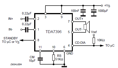
I have checked the part number: TDA7396 and it's datasheet.
as you can observe, it has short circuit dump and thermal protection as per fig.2
it has also clipping detection and for that In order to use this function, the CDDIA pin (#4) has to be resistively connected to a positive voltage reference (between 5V and Vs).
I did buy some step down DC converters but I did not add them in my first design. So what I get from this is placing 5v or above on pin #4 will enable the circuit protection? Is this what it's saying? I do remember once AG said you could put the 16v on it.
Brzrkr
I did buy some step down DC converters but I did not add them in my first design. So what I get from this is placing 5v or above on pin #4 will enable the circuit protection? Is this what it's saying? I do remember once AG said you could put the 16v on it.
Brzrkr
Well, that's a disappointing response. That's some pretty vague, unclear language in my book.
We already knew it was suitable to use in car stereos - it's specifically marketed for that exact purpose! I also already knew that it has various forms of protection on the outputs - that's clearly described in the datasheet. What we needed to know was what protections, if any, it has on the inputs. As for car connections, we need to know if it can be fed from the speaker level output of another amplifier, as opposed to a line level signal.
It might be worth one more shot trying to clarify your question for them and see if you get anything more meaningful out of them. As it stands, I don't think we know anything more than we did a week ago.

 Facebook
 Google
 GitHub
 Linkedin