Joule Thief - Questions on the transformer / Inductor

Thread Starter

circuit9

Joined Sep 10, 2017
26
You are absolutely right to suspect the results of computer simulation.

I duplicated your circuit with real parts. It works very well with 1.21 volts in, the only voltage I tried. The transistor is a 2N4401 and the resistor is 4.7k -the closest I could come to 5.6k. The capacitor is polyester film.

View attachment 135187

In the photo the inductors are 5 cm apart and at right angles (for minimum mutual inductance). Regardless of orientation or how close together the two inductors are there is no visible change in the luminance of the LED.
Thank you for the time & effort to build the circuit. So the inductors does not need to be near or coupled.
Could it be this type of inductor had wire coil, that why no coupling is needed.
https://www.amazon.com/15pcs-Surfac...UTF8&qid=1505871342&sr=1-65&keywords=inductor

this type of inductor need to be close for coupling
https://www.amazon.com/gp/product/B005XIKI1U/ref=oh_details_o00_s00_i00

this type of inductor is lossy so cannot be use
https://www.amazon.com/Inductor-Val...UTF8&qid=1505871493&sr=1-92&keywords=inductor

Meanwhile I will experiment this 3 type of inductor.

As a noob or newbie to EE, I really appreciate your effort / time / patience to teach.
 

DickCappels

Joined Aug 21, 2008
10,662
The first inductor to which you linked -the drum core inductor from is designed for use in switching power supplies and it has lower resistance making it a good choice for a low frequency LC tuned circuit.

The second -the axial lead inductor is good for filtering, particularly when you don't need to have low resistance. Some video filters can use this but I think I would use this in low power power supply filtering.

The third -the chip inductor, I agree. Not intended for high Q (low loss) operation, though I have used them in some UHF oscillators but not to set frequency. They might work in your circuit with the right capacitor, but the bobbin inductors are best for this kind of use and that is what you find in a lot of bright LED flashlights.

Bottom line...For the second two your best way of finding out is what you intend to do anyway, which is to experiment.

[QUOTE="circuit9, post: 1179905, member: 473960" (Most text removed for clarity) So the inductors does not need to be near or coupled.
.[/QUOTE]

But they are coupled by virtue of them being wired in series. During part of the cycle energy is transferred to one and then back to the other.

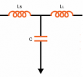
The circuit contains a version of this three component circuit:
upload_2017-9-20_14-24-51.png
It is equivalent to a delay line, like a piece of coaxial cable but physically much smaller, with one end shorted and connected to the battery in your schematic).

The transistor's collector drives one end of the delay line and the negative pulse travels down to the end of the line that is shorted and the pulse is reflected back towards the transistor collector. The transistor's base is connected to the middle of the delay line with that 5.6 k resistor. At some frequency, determined by the values of the capacitor and the inductors, the signal reflected from the grounded end of the delay line to the base resistor is 180° out of phase with collector pulse (it is positive-going) and this reinforces the transistor being on. That is the "push" that sustains oscillation, those pulses racing from one end of the network to the short and back to the collector (and capacitor) is what couples the inductors.

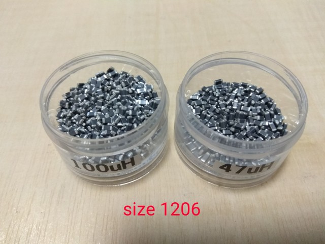
One thing that bothers me: Those flat surface mount inductors looked pretty small to be 100 uH. Do you have any way to measure them?

I think you will do well in your study of electronics.
 

Thread Starter

circuit9

Joined Sep 10, 2017
26
One thing that bothers me: Those flat surface mount inductors looked pretty small to be 100 uH.
I bought these flat inductor from ebay. Selecting the size 1206 & inductance value I want & they arrived, labelled as such.
I would be glad to send you some these inductor if you give me your mailing address.

Do you have any way to measure them?
My DMM cannot measure inductance.
 

Thread Starter

circuit9

Joined Sep 10, 2017
26
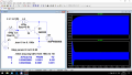
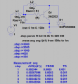
See Kcoupl 0 and 0.95
Thank you the picture. Is this the picture what Dick is describing below
The transistor's collector drives one end of the delay line and the negative pulse travels down to the end of the line that is shorted and the pulse is reflected back towards the transistor collector. The transistor's base is connected to the middle of the delay line with that 5.6 k resistor. At some frequency, determined by the values of the capacitor and the inductors, the signal reflected from the grounded end of the delay line to the base resistor is 180° out of phase with collector pulse (it is positive-going) and this reinforces the transistor being on. That is the "push" that sustains oscillation, those pulses racing from one end of the network to the short and back to the collector (and capacitor) is what couples the inductors.
 

DickCappels

Joined Aug 21, 2008
10,662
To give some closure to this, there was some investigation done outside the forum and it was found that although the packages of inductors that the TS received were marked with specific values the contents were mixed values and some of the prototypes were made using comfinations if
Inductor values that did not oscillate. The very low Q of the inductors might have kept some combinations from oscillating, though this later aspect was not investigated.

Bottom line: The circuit worked fine using chip inductors when they were the correct value.
 

takao21203

Joined Apr 28, 2012
3,702
I bought these flat inductor from ebay. Selecting the size 1206 & inductance value I want & they arrived, labelled as such.
I would be glad to send you some these inductor if you give me your mailing address.

My DMM cannot measure inductance.
Pretty much look like ferrite beads to me.

Sometimes I crush open parts if I have doubts but actually I have inductivity testers.
Also theres a two transistor torch circuit, only needs one inductor.

Most inductors are coated and from the picture doesnt look like epoxy coating at all. The inductors look very specific when they are coated and when they arent, as for very tiny kinds usually they are square and you can see ferrite + coil + recognize its copper by the appearance.

A tiny 4x magnifier is highly useful for these SMDs even to be able to read the imprint, often I mislay them so I have in use at least 3 or so, difficult to get a large glass with 4x or more, but the tiny magnifiers i got on ebay some years ago, recommend to get a few so you can find at least one or youll be almost helpless to identify small SMD properly or a SMD IC solder joint.
 

DickCappels

Joined Aug 21, 2008
10,662
That seems to say that although the curcuit works without the inductors coupled, it looks a lot better with coupling.

Thank you for your a analysis.
 
Top