JK flip-flop counter on breadboard not working

Thread Starter

johnlenar1

Joined Apr 11, 2022
1
Hi all, first post here.

I simulated a counter activated by a switch on falstad : starting with all LEDs off, then LEDs ON one at a time, 1. first LED on, 2. second LED on, 3. third LED on, then 4. button push turns LEDs off (reset). Here is the link to that simulation : https://tinyurl.com/y7cexevw

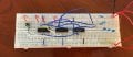
The problem I am having is recreating it on a breadboard. I have attached my work down below. Used on the breadboard are 2 JK flip-flops (XD74LS76) and 1 AND gate (XD74LS08). I am using 9V battery on breadboard. In simulation I used 5V (Not sure if that matters).

I am no expert in JK flip flops or counters, and pretty new to simulating / building as a whole, so I am eager to learn what I am doing wrong here.

Thanks for the input.
 

Attachments

MrChips

Joined Oct 2, 2009
30,712
Welcome to AAC!

I see problems:

1) 74LSxx ICs cannot run on 9V. You need 5V ± 0.25V

2) You cannot test a flip-flop with a pushbutton alone. There is something called switch-bounce which you need to look up.
 

crutschow

Joined Mar 14, 2008
34,285
I am using 9V battery on breadboard. In simulation I used 5V (Not sure if that matters).
Yes, it certainly does (matter).

I suggest you look at the data sheets for the devices you have to see their maximum ratings before you use them.
That will save a lot of grief and keep the magic smoke inside the components. :rolleyes:

If you want to use a 9V supply, then you can substitute CD4000 series devices which can operate up to 15V.
 
Last edited:

sagor

Joined Mar 10, 2019
903
Also, a 74ls chip may not be able to source enough current to light the LEDs. They can sink more current than they can supply. Even then, a 74LS76A can only sink about 8ma. That may be just enough to light up a LED (most LEDs)
Also, if you put 9V on a 74LS76 chip, you may have blown the chip, it is not supposed to run with more than 5V, though it may tolerate up to 5.75V
 

MrChips

Joined Oct 2, 2009
30,712
Problem #3

I didn't go so far as examining the rest of the circuit.
Never drive LEDs from a logic output and hope to send that logic level to another input. Use a buffer such as 74LS04 to drive the LED and nothing else.
 

DickCappels

Joined Aug 21, 2008
10,152
Edge triggered devices don't really work if your power supply is not bypassed adequately or if your grounding isn't good.

This article might be of some help: https://www.allaboutcircuits.com/te...ry-ic-part-1-understanding-bypass-capacitors/. (This item is absolutely critical to the proper operation of your circuit.)

Those plug-in breadboards are not exactly great for handling high speed signals. Even though you might press the button up to several times a second the flip-flops can respond to millions of pulses per second and with rise and fall times in the tens or hundreds of nanoseconds, it is very easy for the edge of a pulse to wind up in the "wrong" part of the circuit, making it misbehave terribly. You might have to resort to soldering this circuit together, taking care to carefully route the connections and avoid ground loops in order to get it to work correctly. I'm not trying to discourage you, only to prepare you to identify where your problems might crop up.
 

crutschow

Joined Mar 14, 2008
34,285
Another advantage of CD4000 devices for this application, besides a wide voltage operating range, is that they are relatively slow, so are less affected by noise or spikes on the power rail.
 
Top