Does anyone know of an elegant way to reset this mod-60 flip flop counter?

Thread Starter

nn44

Joined Dec 18, 2024
4
Sorry if this has been answered before, I've already tried searching the forum and haven't been able to find anything yet.

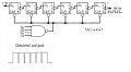
If I chain 6 j/k flipflops together and use something like a 4 input nand gate I can construct a mod-60 counter that will take for example a 60hz input and provide a 1hz output.

What I'm trying to achieve is after it hits 60 and the output flips have it immediately reset on the next clock input pulse.

I.e. one state for 1hz opposite state for only 1/60hz. etc.

i attach a picture of my overall design idea which should produce an even 1hz on / off output and a mock waveform of the desired output I wish to achieve.

Any pointers or advice would be greatly appreciated. Perhaps I can combine the nand with the clock signal and reset it that way but it has been many years since i've worked with logic gates and this is just a curiosity project that came about as a result of finding a box full of old logic chips while having a clearout.

Kind Regards.
 

Attachments

WBahn

Joined Mar 31, 2012
32,706
You need to be very careful about the approach you are trying to take -- asynchronous logic requires very careful consideration of race and glitch conditions. There are a lot of demons that lurk in those waters.

Could you explain more about your mock output? Do you really need/want it to have such a high duty cycle? You don't want a 1 Hz 50% duty cycle output? If so, then what are your constraints one how short and how long the LO period can be each cycle?
 

Thread Starter

nn44

Joined Dec 18, 2024
4
Hey, thank you for your reply!

Correct. I don't want a 50% duty cycle. Yes, I figured asynchronous logic could lead to a lot of weird conditions.

Ideally I'd like the LO to be one cycle of the input clock. so 59/60 are logic high, 1/60 logic low (or vice versa).
 

Thread Starter

nn44

Joined Dec 18, 2024
4
Thinking about this I can just use the reset signal as the momentary pulse I was looking for. I will try that!
 

WBahn

Joined Mar 31, 2012
32,706
Thinking about this I can just use the reset signal as the momentary pulse I was looking for. I will try that!
That will be a VERY momentary pulse, probably measured in nanosecond-scale time frames, depending on the logic family you are using.
 

Art Vandelay

Joined Nov 1, 2024
140
You can use two 4017 IC to divide 60Hz to 1Hz. One time I made a circuit that used 60Hz mains noise as the clock source with a small piece of wire as an antenna. It worked surprisingly well given the clock signal was very low power AC noise! I can provide a simulation to get you started.
 

AnalogKid

Joined Aug 1, 2013
12,047
Sticking with the schematic in the original question -

First step: Because 000000 is a valid output state, you want to decode a count of 59 (dec). The output of this decoder will be true for exactly one input clock cycle. To make an even more narrow output pulse and prevent race problems, include the input clock in the decoder so its output is true only for the second half of an input clock cycle.

Second step: Use the trailing edge of the decoded 59 signal to reset the counter. This is done with a differentiator circuit to produce a very short Reset pulse. This places the Reset action at the *end* of the 60th count, not the start, so there is no nanosecond race issue.

ak
 
Last edited:

Thread Starter

nn44

Joined Dec 18, 2024
4
That will be a VERY momentary pulse, probably measured in nanosecond-scale time frames, depending on the logic family you are using.
Sticking with the schematic in the original question -

First step: Because 000000 is a valid output state, you want to decode a count of 59 (dec). The output of this decoder will be true for exactly one input clock cycle. To make an even more narrow output pulse and prevent race problems, include the input clock in the decoder so its output is true only for the second half of an input clock cycle.

Second step: Use the trailing edge of the decoded 59 signal to reset the counter. This is done with a differentiator circuit to produce a very short Reset pulse.

ak
Thank you both for the replies, good ideas and I hadn't even thought about how short the pulse would be, I naively assumed it would be one input clock cycle as the reset signal comes from a nand gate.. but yes it will reset the counter!

Given me some good ideas and things to consider, I think I can make something work now! Thanks again.
 

AnalogKid

Joined Aug 1, 2013
12,047
Second step: Use the trailing edge of the decoded 59 signal to reset the counter. This is done with a differentiator circuit to produce a very short Reset pulse. This places the Reset action at the *end* of the 60th count, not the start, so there is no nanosecond race issue.

ak
 

MisterBill2

Joined Jan 23, 2018
27,186
Second step: Use the trailing edge of the decoded 59 signal to reset the counter. This is done with a differentiator circuit to produce a very short Reset pulse. This places the Reset action at the *end* of the 60th count, not the start, so there is no nanosecond race issue.

ak
Really, us the rising edge "59" to enable a oneshot, and falling edge ti trigger the OS to deliver the reset pulse. With the right pulsse width the 000000 count will be the correct width, and the reset pulse will be wide enough to reset even a ripple counter. Beware that as a ripple counter each section will be delayed a bit more, so setup times may lead to unexpected operations.
 
Last edited:
Top