Does anyone have a better solution for this design?

Thread Starter

blnc

Joined Mar 19, 2025
3
Hello everyone!:D

I’m working on a quality control setup for a project that measures temperature with PT1000 sensors. Each device has 4 sensors, and I need to test 4 devices at the same time, so that’s 16 sensors total. To do that, I need to simulate different resistance values that correspond to temperature readings.

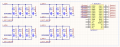
Right now, I’m going with a setup where precision resistors are switched using MOSFETs, all controlled by a 16-channel SPI I/O expander to avoid wasting too many MCU pins. This keeps it simple, avoids mechanical relays (which are slow and wear out), and lets me control everything from an STM32. The attached image shows the setup for just one device, so I would need three more of these and i wonder if theres a way to make it simpler.

I've looked into analog switches and digital pots but they all had issues (extra resistance, limited range or just low precision). The MOSFET + SPI expander setup seems like a good balance between accuracy, speed, and reliability, but before I lock it in, I wanted to ask:

Is there a smarter way to do this?
 

Attachments

crutschow

Joined Mar 14, 2008
38,316
On way to do a measurement with multiplexers (which was done on a satellite I worked on) is to have an accurate, constant-current excitation switched by one mux channel to the UUT, and two other mux channels (typically by a dual channel mux), used for a 4-wire measurement to the measurement input.
That way the mux resistance doesn't affect the measurement, since the constant-current is insensitive to it, and the measurement input has a high enough impedance, that typical mux resistance has no significant effect on the measured voltage.
Using a constant-current also makes the sensor output voltage directly proportional to its resistance.

Thus 16 sensors would require one 16-channel mux for the current and two dual 8-channel for the voltage measurement, plus one constant-current source.
A stable/stiff current-source can be made with one op amp, one transistor, and a voltage reference IC.
 
Last edited:

JohnSan

Joined Sep 15, 2018
121

There is likely to be a device that will be used for the conversion of the measurement taken from the PT1000 probe.

Depending on what that device is, making suggestions on the circuit proposed so far, may fall well short of a reasonable solution.

But you enjoy 20 question guessing games.....
Carry on.
 

crutschow

Joined Mar 14, 2008
38,316
There is likely to be a device that will be used for the conversion of the measurement taken from the PT1000 probe.
That would likely be an A/D converter.
Depending on what that device is, making suggestions on the circuit proposed so far, may fall well short of a reasonable solution.
How the sensor signal is multiplexed is unlikely to be significantly affected by how the signal is measured.
Carry on.
Thanks for your permission to do that. :rolleyes:
 
Last edited:

MisterBill2

Joined Jan 23, 2018
27,164
OK, it appears that you will be testing the measurement circuits, not the actual devices. So the first question is "what are you testing for??", Calibration Accuracy??, functionality?? Linearity?? or stability??. Second question is how much time do you have for the test?? That depends on the production rate.
But now it is confusing because it says " and I need to test 4 devices at the same time, "... So are you actually testing the temperature sensors?? Or the devices that read the sensor resistances??? Please clarify that.

For starters, I suggest one permanent resistor of the highest value, with additional resistors switched in parallel to provide the lower values. This will allow a tester self check with every test done.
I will have more helpful advice when these answers are known.
 

Thread Starter

blnc

Joined Mar 19, 2025
3
OK, it appears that you will be testing the measurement circuits, not the actual devices. So the first question is "what are you testing for??", Calibration Accuracy??, functionality?? Linearity?? or stability??. Second question is how much time do you have for the test?? That depends on the production rate.
But now it is confusing because it says " and I need to test 4 devices at the same time, "... So are you actually testing the temperature sensors?? Or the devices that read the sensor resistances??? Please clarify that.

For starters, I suggest one permanent resistor of the highest value, with additional resistors switched in parallel to provide the lower values. This will allow a tester self check with every test done.
I will have more helpful advice when these answers are known.
What are you testing for? Both the functionality and the accuracy of the measurement system, to make sure it reads resistance values within an acceptable error margin. The target accuracy is around ±0.5 °C, which is equivalent to approximately 2 ohms for a PT1000 sensor.

How much time do you have for the test? The idea is that once the operators connect the board, the test should run automatically with minimal intervention so testing multiple boards at the same time would reduce the workload. It doesn’t need to be the fastest, but it should be efficient.

Are you testing the sensors or the devices that read the sensor resistances? I'm testing the devices that read the sensor resistances, not the sensors themselves.
 

Thread Starter

blnc

Joined Mar 19, 2025
3
Thanks for all the responses you guys, some of them have been really helpful in improving the current design and fixing issues I had. :)
 
Top