Jet/Pressure washer issues - circuit testing advice needed

Thread Starter

Themusicman

Joined Apr 2, 2017
48
Hi All

I have a jet/pressure washer that doesn't seem to want to go! and I need some advice on testing to see what is knackered. The thing is, it's 240V AC and I would prefer advice from experts on here before I test things please.

Here's a schematic diagram of the wiring, it's a diagram from the web but I have added the capacitor to the diagram, and it reflects 99% accurately the wiring inside the unit. (except there is an earth cable from the plug connected to the motor chasis)


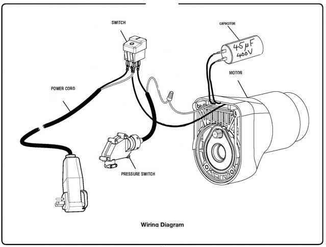
When I power the unit on, nothing happens. There is (was) 240V AC power across the left hand set of contacts on the switch when I turned it on, and the pump jolted a few mm, but then that was it. I then found that the 3A fuse in the mains wall plug was blown.

Personally, I don't like the look of a 400V capacitor, and want to know if I can test it in any way before I put either a replacement 3A or 13A fuse in it (which one?).

There's no burning smell, nor is there any sign of overheating or heat damage. I have a picture of the capacitor if anyone wants to see it.

Does anyone have any idea what the issue might be, and what I should test to determine what's wrong please.

Thanks
 

AnalogKid

Joined Aug 1, 2013
12,077
If the pump was put away wet, the pump mechanism could be frozen. That would account for the mm of movement followed by a blown fuse.

ak
 

MaxHeadRoom

Joined Jul 18, 2013
30,589
You can give the cap a rough test by disconnecting and placing a meter on resistance range and place across the leads, you should see no short circuit but see the range slowly changing over time until it eventually settles, then reverse the leads, you will see a high reading and this will slowly decay.
If you get this it looks like it could be OK.
The alternative is to sub the cap.
If you can access the motor shaft, you could give it a flick when starting, this would confirm may be the cap if it does not run, also the motor should be free to turn, obviously.
Max.
 

Thread Starter

Themusicman

Joined Apr 2, 2017
48
You can give the cap a rough test by disconnecting and placing a meter on resistance range and place across the leads, you should see no short circuit but see the range slowly changing over time until it eventually settles, then reverse the leads, you will see a high reading and this will slowly decay.
If you get this it looks like it could be OK.
The alternative is to sub the cap.
If you can access the motor shaft, you could give it a flick when starting, this would confirm may be the cap if it does not run, also the motor should be free to turn, obviously.
Max.
I can access the to pof the motor, and though I wouldn't want to use my fingers to try this, I'd use something to give it a nudge.

Thanks, I'll try this.
 

LesJones

Joined Jan 8, 2017
4,511
The motor will probably have two windings. The run winding will be connected directly across the mains. The start winding will be connected across the mains via the capacitor and probably a centrifugal switch. When the motor is near its operating speed the centrifugal switch opens so the start winding is no longer connected to power. Assuming that you have a multimeter you can do some resistance measurements. (With it NOT connected to power.) Start by disconnecting one of the wires going to the capacitor. (Either one.) Measure the resistance between the wire from the motor to the on/off switch and the wire from the motor to the presure switch at the screw on connector. (I would expect a reading between about 5 and 20 ohms.) Now measure the resistance between the points on the motor where the capacitor connects to. This will be the sum of the resistances of the start and run winding via the centrifugal switch. (Expect this reading to be three or four times the first reading.) Report these readings in your next post. You can do a very rough test on the capacitor by measuring its resistance. First short the wires from the capacitor together for a few seconds to make sure it is discharged. Now connect it to your multimeter. You should see a lowish resistance at first which should increase to a highe value after several seconds. (It may finish up at about 220K as some capacitors have a built in resistor tpo discharge them.) Even if the capacitor readings are like this it does not mean that is completely good.

Les.
 

tcmtech

Joined Nov 4, 2013
2,867
Personally, I don't like the look of a 400V capacitor, and want to know if I can test it in any way before I put either a replacement 3A or 13A fuse in it (which one?).
13A. If it was a 3A that would be why it blew. Until you try it again with a good and correctly sized fuse I would not put too much thought into things. Fuses do get weak with age and blow despite not having been over loaded long enough to normally take them out.
 

Thread Starter

Themusicman

Joined Apr 2, 2017
48
Well folks, the good news is that it's now working again! Well, it's working while it's all apart!!! I think it must have been the pressure sensor. I can'tr recall which position it was in when I took it all apart, but I made sure that was working (mechanically at least) and I guess it was stuck in the failsafe position. I shall wait until the morning to see if it all works whewn I put it back together.

Thanks to everyone who helped and commented.
 
Top