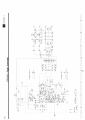
Those are kind of odd caps to blow, seems to me. They're in the right channel input section, one at the inverting input to U101-A, the TL072 opamp, the other across the feedback path of the same side of the opamp.
What did you do, give it too high of a level of audio input?
I think I'd pull C101 and C102 and test to see if they have excessive leakage current.
OK, now what is needed are some detailed photos of the "problem areas."
You're going to need something better than a scanner or your phone's camera, though.
Do you see the tops of any of the capacitors bulging upwards, or any capacitors (those with aluminum tops) with holes in their tops? When electrolytic caps go bad, they generally just pop open. This is due to excessive leakage current. The leakage current between the layers of plates in the capacitor causes heat, and the heat boils the liquid electrolyte. As a result, the package ruptures. Normally, the top of the capacitor has little lines which are deliberately weakened areas. The idea is that the package will open up sort of like a flower instead of fragmenting like a bomb.
yes, i think i gave it a bit too much.
i have had a look at all of them but they all seem fine, the wiring chart says that they should be ceramic do you think that is a typing mistake?
do i need to take them out to check or can it be done insitu?
i will get some proper pictures tomorrow.
thanks for your help.
Try using better illumination, and be further away from it. Your cell phone has a tiny lens.
If you can't get decent lighting indoors, taking pictures on an overcast day works wonderfully. The lighting will then be very even, and you will not see shadows. Otherwise, taking photos in sunlight will result in a very harsh image with very dark shadows and strong reflections.
Craig,
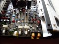
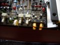
The photos are still so fuzzy that all I can make out are blobs of color - except for the 1st photo in the last group of two, I could make out a resistor that was perhaps a foot further away than the area you targeted.
Unless you can get some better photographs, we're not going to be of much help.
If they're not well-focused, I'm afraid they're useless.
I see several fuzzy blue colored things.
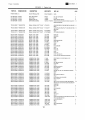
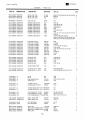
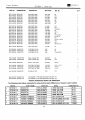
You can look it up on the parts placement diagram; which is the sheet where you initially made pointers to the caps you replaced.
What is the reference designator of the relay?
It will probably have a reference designator starting with RL... or perhaps X..., and will likely be rectangular.
I hate to thread dig and normally would never (Im around many boards) but I have this same issue.
Actually it may be very possible I bought this very amp via E Bay (lol).
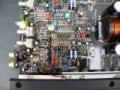
C107 was blown on my amp also. Looking at the schematic provided is surely looks like a ceramic cap.
But whats blown is actually a round capacitor. The board shows a circle on the mount and a + symbol for a leg.
Heres my pics:
I am hoping someone can help me out with this. JBLs tech department has confirmed twice now "CAPACITOR CERAMIC TUBULAR 50V 102pF cap". However Im not finding such a ting (im a novice).
What I pulled out was a lot of "hair", two legs with a rubber separator, some foil... lol
 Facebook
 Google
 GitHub
 Linkedin