Facebook
 Google
 GitHub
 Linkedin
Hi all,
Noob here with a couple of questions,
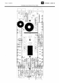
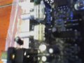
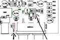
I have lost the audio output on my amplifier and the protection light is on, looking at the amp it appears two 22yf 16v resistors have blown, what now does it matter which way round you fit these and also i have been told that the output transistors(?) could be blown also.
I have the repair manual but it doesnt mean much to me, please help.
Thanks,
Craig.
Noob here with a couple of questions,
I have lost the audio output on my amplifier and the protection light is on, looking at the amp it appears two 22yf 16v resistors have blown, what now does it matter which way round you fit these and also i have been told that the output transistors(?) could be blown also.
I have the repair manual but it doesnt mean much to me, please help.
Thanks,
Craig.