Facebook
 Google
 GitHub
 Linkedin
Ryan from Ohio
- Joined Mar 8, 2009
- 6
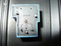
I would also like to point out, if you look at his attachment in post 32 you can make out the location. Look closely it shows a rectangle.
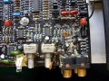
My amp in location C108 is a round part that looks like a CAP. It has the negative leg marked, its 16V 10uF. The board then has the + hole marked and the cap is in properly. There is clearly a mistake somewhere...
C108:

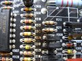
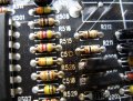
C406 and C111 are little yellow colored "things" that resemble a resistor...C406:

C111:

I have probed JBLs parts person and they are sure its whats listed. There obviously was a change made somewhere... Not documented of course.
These amps are only made to take 5V inputs. Some Head units are capable to 8V and then you have line drivers upto 13V... So im assuming someone over did it.
My amp in location C108 is a round part that looks like a CAP. It has the negative leg marked, its 16V 10uF. The board then has the + hole marked and the cap is in properly. There is clearly a mistake somewhere...
C108:
C406 and C111 are little yellow colored "things" that resemble a resistor...C406:
C111:
I have probed JBLs parts person and they are sure its whats listed. There obviously was a change made somewhere... Not documented of course.
These amps are only made to take 5V inputs. Some Head units are capable to 8V and then you have line drivers upto 13V... So im assuming someone over did it.
Last edited:
")