Jacob's Ladder: timer circuit keeps getting fried

Thread Starter

wikenator

Joined Oct 8, 2014
7
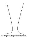
I built the desktop Jacob's ladder from the pdf files found on the Thinkbotics website (http://www.thinkbotics.com/products.htm http://www.thinkbotics.com/jacobs-ladder-article.zip). However, I am not getting a Jacob's ladder effect from the device; it is more like a spark gap. I've tried different shapes for the electrodes (wider, narrower, different angles, etc.), but the electricity only likes to hang out at the closest gap in brief arcs. The repetition rate pot does change the frequency of sparks, but the arc does not rise at all. I modified the circuit to run off of a 12-volt wall wart, and measurements with a KVM show that the circuit is getting pretty close to 12 volts. The major problem I am experiencing right now is that after switching the device on, I only get about 3 or 4 arcs before the 556 IC burns out; no matter what the repetition rate or trim pot is at, the IC just fries. I've tested the transistors and diodes as well, and they all seem fine. Any suggestions for troubleshooting? I linked some photos of my circuit as well. (https://www.wandkr.com/special/IMAG0608.jpg https://www.wireandkloudready.com/special/IMAG0609.jpg https://www.wandkr.com/special/IMAG0610.jpg https://www.wandkr.com/special/IMAG0611.jpg )
 

Sensacell

Joined Jun 19, 2012
3,442
Jackob's Ladder effects are caused by the arc heating effects, if your power source does not produce enough power, it will not generate enough heat for the effect. Hot air rises!

Use a neon sign transformer- easy.
 

alfacliff

Joined Dec 13, 2013
2,458
get a plastic or glass tube large enough to fit over the "jacobs ladder" leave a little gap at the bottom for air to get in,. the heated air will move the spark up the "ladder".
 

Thread Starter

wikenator

Joined Oct 8, 2014
7
You might try adding a large capacitor (say 100 Ufd.) from pin 14 to pin 7. The + goes to pin 14.
I am assuming I should add a polarity-sensitive capacitor? and 100 µF?

get a plastic or glass tube large enough to fit over the "jacobs ladder" leave a little gap at the bottom for air to get in,. the heated air will move the spark up the "ladder".
I already constructed a glass tube to fit over the electrodes, I just had it removed as I was adjusting the gap between them. :)
 

Thread Starter

wikenator

Joined Oct 8, 2014
7
Jackob's Ladder effects are caused by the arc heating effects, if your power source does not produce enough power, it will not generate enough heat for the effect.
I am currently using a 12V 1A wall wart to power the ladder. Do you think using a power supply with 2A or more would be useful? Would I just add up all of the power ratings of my components to see how much the circuit can handle before the parts start to melt?
 

ronv

Joined Nov 12, 2008
3,770
Yes, a polarized cap like the big timing cap in your picture.
The coil could draw several amps (6-8) depending on how long it is on before the spark, so bigger would be better. Same with the added cap.
 

Thread Starter

wikenator

Joined Oct 8, 2014
7
Thanks, ronv! The circuit no longer burns out the timer.

However, I am still not getting the arcs to be "hot" enough. I can crank up the repetition rate until the arcs jump fast enough to look 'solid', but there is still no climbing effect. Would a larger wall wart be a solution? I've also tried widening/narrowing the gap between the electrodes and still the electricity likes to hang out near the narrowest point.
 

bertus

Joined Apr 5, 2008
22,276
Hello,

From most designs of jacobs ladders, I see that the wires are narrow at the bottom and getting wider spread towards the top.
I made a little sketch on how the wires could be:


Bertus
 

Attachments

Thread Starter

wikenator

Joined Oct 8, 2014
7
Hello,

From most designs of jacobs ladders, I see that the wires are narrow at the bottom and getting wider spread towards the top.

Bertus
Yes, I have tried that configuration, but the arc just wants to jump between the narrowest spot at the bottom. I have also tried an almost parallel configuration as described in the original project specification, but then the arc likes to jump at the very top of the wires instead.
 

ronv

Joined Nov 12, 2008
3,770
A larger wall wort wouldn't hurt. It will need to be covered. Make the bends gentle and smooth, if there is a place that is a lot closer it will always are there.
 

Thread Starter

wikenator

Joined Oct 8, 2014
7
Finally hooked up the ladder to a 2A power supply, and I got much stronger arcs. They even travelled almost the full length of the wires! I realized that the original project used AA batteries for power, and that 1A of current was probably not going to cut it in this circuit.

However, after a few seconds the timer got burnt out again. I currently have a 100 uF capacitor betwen pins 7 and 14 on the IC; perhaps a larger cap would be better with the increased power?
 

ronv

Joined Nov 12, 2008
3,770
Yes, another one would be twice as good. If that doesn't fix it we will need something better.
One other thing to look at:
The + for the coil should go right to the switch if you can do that. It should not go thru a lot of wires on the board.
The same is true for the ground on the FET.
 

DerStrom8

Joined Feb 20, 2011
2,390
1A is most likely not enough. 2A is probably the absolute lowest I would go. Ignition coils usually try to draw about 5 or 6 amps, so you should get a power supply that can source that. You're not going to get very hot arcs with only 1A.
 

DerStrom8

Joined Feb 20, 2011
2,390
Hello,

From most designs of jacobs ladders, I see that the wires are narrow at the bottom and getting wider spread towards the top.
I made a little sketch on how the wires could be:


Bertus
The width and overall shape of the "ladder" depends on the voltage and current your coil can supply. A wider "V" is better for high-current transformers, otherwise the gap will become too wide too fast and the arc will extinguish not far from the base.
 

Thread Starter

wikenator

Joined Oct 8, 2014
7
I moved the + wire leading to the coil from the board straight to the switch. I added a bigger capacitor between pins 7 and 14 of the IC (~500 µF now). And I got a 12V 6A power supply to power the ladder. I am getting fairly strong arcs when the repetition rate is turned up high; I am still playing with the trim pot settings and the optimal shape of the ladder electrodes. Thank you for all the assistance!
 
Top