 Facebook
 Google
 GitHub
 Linkedin
Hello everyone,
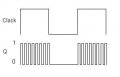
I really need your help here. I have been reading up on logic gates, latches and flipflops, however there's a little thing that is still confusing about the J-K flipflop. I know that idealy, if both the J and K inputs are held high and the clock input strobed at some frequency, the outputs (Q and notQ) would toggle at each rising edge of the clock input (assuming a positive edge triggered flipflop); but what would happen if the clock signal is not strobed, but rather a square wave with a 50% dutycycle of very low frequncy (or even the clock input just held HIGH!)? Wouldn't the outputs both be unstable, and therefore oscillate rapidly during the HIGH state of clock input?
I'm not sure if there's circuitry in the dedicated J-K flipflop chips to prevent this kind of thing happening, but suppose I were to build one from descrete logic gates. Would it oscillate like I described? I'm mainly interested in wheather the flipflop has some kind of natural tendency to reject unstrobed clock inputs.
The total delay time from the input of the AND gates to the output of the NOR gates may be as little as 3.552x10^-8 seconds, which means if the clock signal goes HIGH when output Q is high (flipflop SET), that would be the maximum amount of time we would want the clock signal to remain high (before Q and not Q change states) otherwise the flipflop would reset and set over and over again because the feedback from the output would reach the inputs of the AND gates faster than the clock is switching.
Long story short, what would the recommended high time of the clock input signal be for a J-K flipflop?
I'm trying to build a bipolar stepper motor driver using a 2 bit synchronous counter (implemented by J-K flipflops) whose output if fed to a decoder circuit. The decoder will drive 2 H-bridges using high power bjt's (TIP41 and TIP42 to be exact or darlington pairs). I'm planning on suppling the counter clock with pulses from a 555 timer.
I'm not sure if you get me, but I hope the sketch I attached will clear things out.
Appreciate you time.
Attachments
-
 5.8 KB Views: 31
")


