 Facebook
 Google
 GitHub
 Linkedin
Hi All,
I am having some issues with a high frequency active clamped flyback converter I have designed. I have pinpointed the issue to either the clamp capacitors, or the current transformer. I am unsure whether the current transformer is saturating, which causes the clamp capacitors to not work properly, or the clamp capacitors are too small causing the current transformer to saturate.
I have attached some images to this post, which show a few things:
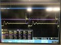
1) VDS across the main switch. I have verified that the upper switch is also switching correctly.
2) Probe setup (Differential) for measuring across the clamp capacitor. Also shows the current transformer that is connected to VDC and the top of the clamp capacitors.
3) Clamp capacitor voltage and current transformer sensed current.
I am testing with a 30V input voltage. I would expect to see the clamp capacitor (5nF), at some voltage closer to the supply voltage. It is clear that there is something wrong with the clamp circuit, because although the switch seems to be turning on OK, the clamp capacitor voltage is very low.
Furthermore, the current transformer seems to have entered saturation. I am unsure if this is due to the issue with the clamp capacitor, or whether the issue with the clamp capacitor is caused by the current transformer saturation. The converter still seems to be switching OK - there is voltage developed on the transformer, the external resonant inductor and on the diodes/secondary load, although slightly less voltage than I would have expected. This leads me to believe that this is where the problem lies within the circuit. I am using a Texas Instruments demonstration board, switching at 500kHz, and using the current transformer CU8965-ALC. The switching transformer is a planar 750341134, which only has 0.12uH leakage. I placed some more inductance in series with the transformer to see if that made a difference, which is 3.3uH and can be seen in the first image with the main switch VDS.
Does anyone have any ideas on what could be causing these issues? I have done calculations for the transformer and with the low voltage I am testing at the core size should be more than enough to avoid saturation, so I think it has to be the current transformer. I have attached the current transformer schematic too.

SiC
I am having some issues with a high frequency active clamped flyback converter I have designed. I have pinpointed the issue to either the clamp capacitors, or the current transformer. I am unsure whether the current transformer is saturating, which causes the clamp capacitors to not work properly, or the clamp capacitors are too small causing the current transformer to saturate.
I have attached some images to this post, which show a few things:
1) VDS across the main switch. I have verified that the upper switch is also switching correctly.
2) Probe setup (Differential) for measuring across the clamp capacitor. Also shows the current transformer that is connected to VDC and the top of the clamp capacitors.
3) Clamp capacitor voltage and current transformer sensed current.
I am testing with a 30V input voltage. I would expect to see the clamp capacitor (5nF), at some voltage closer to the supply voltage. It is clear that there is something wrong with the clamp circuit, because although the switch seems to be turning on OK, the clamp capacitor voltage is very low.
Furthermore, the current transformer seems to have entered saturation. I am unsure if this is due to the issue with the clamp capacitor, or whether the issue with the clamp capacitor is caused by the current transformer saturation. The converter still seems to be switching OK - there is voltage developed on the transformer, the external resonant inductor and on the diodes/secondary load, although slightly less voltage than I would have expected. This leads me to believe that this is where the problem lies within the circuit. I am using a Texas Instruments demonstration board, switching at 500kHz, and using the current transformer CU8965-ALC. The switching transformer is a planar 750341134, which only has 0.12uH leakage. I placed some more inductance in series with the transformer to see if that made a difference, which is 3.3uH and can be seen in the first image with the main switch VDS.
Does anyone have any ideas on what could be causing these issues? I have done calculations for the transformer and with the low voltage I am testing at the core size should be more than enough to avoid saturation, so I think it has to be the current transformer. I have attached the current transformer schematic too.
SiC
Attachments
-
 1.1 MB Views: 17
 -
 961.6 KB Views: 18
 -
 1.1 MB Views: 18


