Xenon flash issues?

Thread Starter

seanstevens

Joined Sep 22, 2009
323
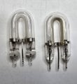
I’m seeing odd behaviour with xenon tubes and trying to pin down what tube parameter might be out of spec.

The beacon circuit has been unchanged and in service for ~25 years. We changed xenon tube supplier last year; all initial tests passed. About six months later, batches of tubes began showing an issue. The beacon PCBA flash rate is 1 Hz, but on 230 VAC / 50 Hz around 70% of the tubes miss every other flash, resulting in an effective 0.5 Hz flash rate.

The strange part is that the same tubes work perfectly on 115 VAC / 60 Hz. Nothing else in the circuit has changed, and all other sections have been checked and are within spec — the behaviour seems isolated to the tube.

Out of ~80 tubes tested, two flashed once and then stopped completely on 230 VAC. When moved to a 115 VAC beacon, they flashed a few times, stopped, then after ~10 seconds began flashing at 0.5 Hz. Moving them back to 230 VAC, they now also show the 0.5 Hz behaviour instead of not flashing at all.

It appears the tubes have no obvious issue on 115 VAC, and that after running for 5–10 minutes, they perform slightly better on 230 VAC (fewer missed flashes), but still not correctly.

Any insights would be appreciated.
 

Thread Starter

seanstevens

Joined Sep 22, 2009
323
I get that, but for now, as stated circuit diagram has not changed in over 20 years - at this time, I am only seeking what could be the tube parameter that is off.
 

Thread Starter

seanstevens

Joined Sep 22, 2009
323
Hi bertus,
Please find attached the datasheet and a photo of the actual xenons. The good one is on the left and the bad on the right.
They look practically identical, except that the bottom of the glass is flat on the good ones and the new ones have a rounded type. Datasheets don't say much to me. The good ones are BUB0641, which shows a particular trigger coil, but the bad one doesn't. The bad ones are U-114. As far as I am aware, the tubes have never been polarised, right? I have tried them the other way around to ensure its not a polarity thing and it isn't.
 

Attachments

bertus

Joined Apr 5, 2008
22,882
Hello,

Looking at the datasheets, the U114 uses a smaller trigger capacitor as the bub0641 ( 0.047 uF vs 0.22 uF ).
It could be that the trigger energy is to high for the U114.
The U114 has a larger trigger surface as the bub0641 ( the gold paint on the tube ).

Bertus
 

Thread Starter

seanstevens

Joined Sep 22, 2009
323
Thanks bertus, yes I see the difference in trigger cap as well as the trigger coil. I will try a cap change and will check.
The silver-painted HT electrodes look identical to each other, in the photo its not shown properly.
 

Thread Starter

seanstevens

Joined Sep 22, 2009
323
Looking at the components used historically on the PCBA, we have always used 47nF for the good tube (BUB0641) and the same HT transformer. So the good tube that states 220nF for the trigger is happily working with 47nF and the same choke. Its just the new tube doesn't seem to like any of them, even though both the cap and the trigger coil used are what is required by this tube.
 

Thread Starter

seanstevens

Joined Sep 22, 2009
323
The source of Xnon tubes is getting scarce. The beacon is a product which has been in use for over 20 years, using the same components, a fairly simple capacitor drop for 230V & 115V. The product is approved by many external approval bodies so we cannot change the components without going through the expensive approvals.
The 2 xenon options are all we have, the normal tube is practically impossible to get and the new one, even though was tested ok, is showing it has a problem.

The alternative tube (U-114) was suggested by the tube manufacturer, not much choice and my MD has gone for the alternative.

Thank you for the link. I know how they work. Whatever the issue is, it is kind of marginal.
 

MrChips

Joined Oct 2, 2009
34,621
Since you are having inconsistent performance from a batch of xenon flash tubes, I would make a test jig to test and characterize each tube. The circuit looks something like this:

1769439826541.png

I would put a Variac on the AC input in order to adjust the input voltage.
Adjust the flash rate in order to give the storage capacitor C1 time to recharge.
 

Thread Starter

seanstevens

Joined Sep 22, 2009
323
MrChip, a good idea, may end up doing that just to satisfy my curiosity, though not sure if it would reveal it even via this test jig.
The manufacturer is Chinese no surprises there. The test batch that we got worked fine, 6 months later not fine anymore. Perhaps one or more of the parameters have changed, and you would never get that out of a Chinese factory.
BTW I monitor that charge cap voltage with a Fluke scope and the charge is fine - in fact, the working units work at 1Hz, 1.5 and 2 Hz, so no issues there in terms of time to charge, we have not had any issues before. My cap is 100uF, and the voltage is around 280V-300VDC across the cap and the xenon.
 

nsaspook

Joined Aug 27, 2009
16,249
Just a wag.

I would suspect gas purity or more likely, changes in gas vacuum pressure between tube types affecting deionization time or trigger energy needed to cause the cascade of breakdowns across the lamp.

The power supply recovery time might (if marginal) be also affected due to increased effective duty-cycle from things like higher peak/avg current during each flash.


https://www.hamamatsu.com/content/d...uments/99_SALES_LIBRARY/etd/Xe-F_TLS1023E.pdf
 
Last edited:

MrChips

Joined Oct 2, 2009
34,621
The value of the charge capacitor C1 should only affect the flash intensity.
What you need to monitor and adjust is the capacitor voltage and the trigger voltage and pulse shape.
 

schmitt trigger

Joined Jul 12, 2010
2,026
Just a wag.

I would suspect gas purity or more likely, changes in gas vacuum pressure between tube types affecting deionization time or trigger energy needed to cause the cascade of breakdowns across the lamp.
Bolding mine, based on costly experience with another gas filled device, a high voltage (15kV) relay.
Let me elaborate; like you, we had to change vendors. The circuit this relay was used had been in production for at least 10 years.
The new relay had identical specifications, and during our validation testing, performed flawlessly. But a few months after its introduction, we noticed a spike in the failure rate.
To cut a long story short, these relays utilize SF6 gas inside a sealed chamber to quench the HV arc. Of course, before filling with SF6, the relay’s chamber has to be totally scrubbed from air, and helium is employed. Helium lately has increased in cost significantly, and the new vendor decided to use nitrogen instead. :eek:Although the residual nitrogen was in the PPM range, it was enough to cause a gradual degradation of the quenching capabilities.
 

BobTPH

Joined Jun 5, 2013
11,463
The original tube lists a repeat frequency of 5 to 250 Hz. The new one lists it as 1 Hz. Assuming that is a maximum, flashing it at 1 Hz is right on the edge, so flaky behavior might be expected.
 

nsaspook

Joined Aug 27, 2009
16,249
Bolding mine, based on costly experience with another gas filled device, a high voltage (15kV) relay.
Let me elaborate; like you, we had to change vendors. The circuit this relay was used had been in production for at least 10 years.
The new relay had identical specifications, and during our validation testing, performed flawlessly. But a few months after its introduction, we noticed a spike in the failure rate.
To cut a long story short, these relays utilize SF6 gas inside a sealed chamber to quench the HV arc. Of course, before filling with SF6, the relay’s chamber has to be totally scrubbed from air, and helium is employed. Helium lately has increased in cost significantly, and the new vendor decided to use nitrogen instead. :eek:Although the residual nitrogen was in the PPM range, it was enough to cause a gradual degradation of the quenching capabilities.
I've seen similar problems with 80kV RF resonators used in semiconductor doping linacs. When the techs don't cycle-purge (pump to high vacuum, back-fill with argon and pump back to high vacuum) the tanks properly before pressurizing the cans to 15psi of SF6 we get all kinds of beam instability issues will internal arcing.
https://forum.allaboutcircuits.com/threads/rigol-dsa815-review.141233/post-1191426
 

Ian0

Joined Aug 7, 2020
13,097
I suspect that either the tube has not extinguished (is still conductive) or the thyristor is still conducting after the first half second.
Try a thyristor which is not as sensitive. It will also have a higher latching current, therefore is more likely to commutate when it should.
Does the 230V version have a full wave rectifier and the 115V version a double half-wave?
 
Top